Size a supply plenum for 500 to 700 FPM and a return or ceiling cavity plenum for 500 FPM or less, then confirm the cross-sectional area with area = CFM ÷ (velocity × 60). That single formula, paired with a velocity target, resolves most of the sizing disputes that stall a set of shop drawings.
The plenum-versus-ducted-return decision comes down to occupancy and construction, not preference. Use an architectural (ceiling cavity) plenum in open-plan offices, retail, and light commercial spaces where the building code permits it and the ceiling void is unobstructed. Choose a fully ducted return instead for healthcare facilities, spaces with exposed combustible framing, or any layout chopped up by full-height partitions that would starve half the return path of airflow.
Both ASHRAE and SMACNA publish the velocity and construction guidance this rests on, but the local authority having jurisdiction always gets the final word on plenum-rated materials and fire separation.
- Supply plenum velocity: 500 to 700 FPM (low-pressure systems)
- Return/ceiling cavity velocity: 500 FPM or less to control noise and pressure loss
- Core formula: area (sq. ft.) = CFM ÷ (velocity in FPM × 60)
- Default choice: architectural plenum for open plans where code allows it; ducted return for healthcare, exposed combustible construction, or heavily partitioned floors
- Verify with: SMACNA duct construction standards, ASHRAE fundamentals, and a static pressure check before releasing drawings
Key Takeaways
Correct HVAC plenum design depends on matching cross-sectional area to CFM at a controlled velocity, then applying SMACNA sealing, ASHRAE pressure guidance, and code-specific fire and smoke provisions before a single register gets balanced.
| Point | Details |
|---|---|
| Match velocity to plenum type | Target 500 to 700 FPM on supply plenums and 500 FPM or less on return and ceiling cavity plenums. |
| Use the area formula every time | Area equals CFM divided by velocity in FPM; verify the result against a static pressure check. |
| Respect the 24 foot rule | Switch to a reducing or split plenum before a single constant-section run exceeds roughly 24 feet. |
| Seal to SMACNA class and test | Mastic-sealed joints and documented leakage testing protect the energy performance the design promised. |
| Specify with fabrication in mind | Provide finished dimensions, sealing class, and access requirements when briefing a shop like Manaracorp for custom rectangular or round ductwork. |
Table of Contents
- Plenum system types and when each is appropriate
- Sizing principles and worked calculations for plenum airflow
- Layout rules, takeoff spacing and trunk length limits
- Materials, fabrication and construction for durable plenums
- Acoustics and performance: velocity, lining, and noise control
- Code and standards for HVAC plenum design
- Installation, commissioning and testing checklist for plenums
- Common problems and troubleshooting for HVAC plenums
- Manara Corp: how a fabricator designs and supplies custom plenums and ductwork
- Thermal performance and insulation impact on plenum design
- Fire safety and smoke control measures specific to plenums
- Integration of plenums with other HVAC components
- Maintenance access and cleaning considerations in plenum design
- What this guide gets right that most plenum advice misses
- Get custom plenums and ductwork fabricated locally in Montreal
- Sources
- FAQ
Plenum system types and when each is appropriate
Every plenum design decision starts with picking an arrangement, and the four you’ll actually specify are the extended plenum, the reducing plenum, the ceiling cavity (architectural) plenum, and the radial or parallel split plenum. Each solves a different combination of trunk length, floor-to-floor height, and airflow uniformity.
An extended plenum is a single, constant cross-section trunk running the length of the mechanical room or corridor, with branch takeoffs tapping off along its length. It’s the simplest thing to fabricate and the cheapest to install, but velocity drops steadily as air peels off at each takeoff, which means the far end of a long extended plenum often starves for CFM unless you’ve sized generously at the supply end.
A reducing plenum solves that starvation problem by stepping the cross-section down after each major takeoff or branch, holding velocity roughly constant along the run. This costs more in fabrication labour (multiple transition pieces instead of one straight box) but delivers far more even airflow across a long run, which matters once you’re pushing air more than 20 to 24 feet from the air handler.
Ceiling cavity plenums, sometimes called architectural plenums, use the space above a suspended ceiling as the return air path instead of a sheet metal duct. The ASHRAE Journal analysis by Taylor documents fan energy savings of 20% to 30% from the lower pressure drop this creates, since the air isn’t fighting duct friction. That savings comes with a real trade off, though: a negatively pressurized ceiling cavity can pull humid outdoor air through unsealed penetrations, and that’s a documented condensation and indoor air quality risk if you don’t manage the pressure balance carefully.
Radial and parallel/split plenums branch supply air outward in multiple directions from a central point, or divide one large plenum into two or more parallel sections. Split plenums show up most often where floor-to-floor height is tight. A study on rectangular plenum chamber geometry found that sectional dimensions and plenum length are the strongest factors driving flow uniformity, and splitting a constrained plenum into parallel sections usually gives you better velocity control than forcing a single narrow, high-velocity box into a shallow ceiling cavity.
Here’s how those trade offs typically shake out by building type:
- Office (open plan): ceiling cavity plenum, provided fire separation and cable ratings are confirmed with the AHJ
- School: extended or reducing plenum for classroom wings; ceiling cavity often works in open corridors and common areas
- Warehouse: extended plenum with radial branches to floor-mounted diffusers; ceiling height rarely constrains design here
- Healthcare: ducted return only; architectural plenums are typically prohibited in patient care areas due to infection control and pressure relationship requirements
Sizing principles and worked calculations for plenum airflow
The math behind plenum sizing is genuinely simple, and that’s exactly why so many drawings get it wrong. Cross-sectional area drives velocity, velocity drives noise and pressure drop, and pressure drop drives fan energy. Get the area right and the rest of the system behaves.
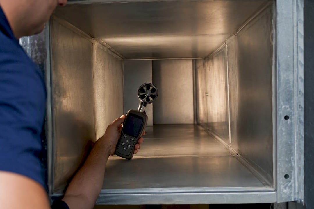
The core formula and its units
The formula is:
Area (sq. ft.) = CFM ÷ (Velocity in FPM × 60)
CFM is cubic feet per minute, the airflow the space needs. Velocity in feet per minute (FPM) is your design target. The 60 converts FPM into feet per second so the units cancel out cleanly, leaving you with square feet of free cross-sectional area, not the outside dimension of the sheet metal box.
That distinction trips people up constantly. If you’re lining the plenum with 1-inch acoustic insulation, you need to add roughly 2 inches to both the width and height of the sheet metal shell to preserve the free area you calculated.
Recommended velocity ranges
Practical guidance from the Askhvac puts supply plenum velocity at 400 to 600 FPM for most low-pressure systems, with 500 to 700 FPM as the broader SMACNA-informed working range once you account for medium-pressure applications. Return and ceiling cavity plenums should stay at or below 500 FPM, since return air paths are more sensitive to noise complaints, and there’s rarely a diffuser downstream to mask turbulence.
Medium-pressure systems can push higher, sometimes into the 1,000 to 1,500 FPM range, but that comes with real constraints: heavier gauge metal, more rigorous sealing (SMACNA Class 1 or better), and acoustic lining or attenuators to manage the noise that higher velocity air inevitably generates. Most commercial plenum work stays in low-pressure territory because it avoids added cost and complexity.
A worked example
Take a 5,000 CFM supply plenum feeding a single air handler discharge, targeting 600 FPM.
- Calculate area: 5,000 ÷ (600 × 60) = 5,000 ÷ 36,000 = 0.139 sq. ft. per… wait, that’s the per-second conversion done wrong in a lot of quick mental math, so let’s slow down. The correct application is Area = CFM ÷ Velocity, where velocity is already expressed as feet per minute and CFM is per minute, so the 60 only enters if you’re converting to feet per second. Using FPM directly: Area = 5,000 ÷ 600 = 8.33 sq. ft.
- Convert to a practical layout: 8.33 sq. ft. equals 1,200 square inches. A plenum 40 inches wide by 30 inches high gives you 1,200 square inches exactly, or you could go 36 inches by 34 inches (1,224 square inches) if the mechanical room favours a taller, narrower profile.
- Check the resulting velocity: 5,000 CFM ÷ (1,200 ÷ 144 sq. ft.) = 5,000 ÷ 8.33 = 600 FPM. That confirms the layout hits your target.
- Validate against static pressure: Run the selected dimensions through a duct sizing calculator or manual static pressure worksheet to confirm the air handler’s fan curve can deliver 5,000 CFM against the total system resistance, plenum included.
Pro Tip: Build a simple spreadsheet with the area formula, a rounding function to the nearest standard sheet metal break dimension (typically whole or half inches), and a velocity check-back cell. It catches transposition errors before they reach the fabricator, and it takes ten minutes to set up once.
The ScienceDirect study on rectangular plenum chambers reinforces something worth remembering here: sectional width and height matter more to flow uniformity than total volume. A shallow, wide plenum and a deep, narrow one can have identical cross-sectional area and wildly different internal flow patterns. When floor-to-floor height won’t allow the depth your area calculation implies, widen the plenum rather than accepting a higher velocity, and leave roughly 400 mm of clearance around inlet and outlet openings so entering air has room to develop an even velocity profile before it hits a takeoff.
Layout rules, takeoff spacing and trunk length limits
Sizing the plenum correctly means nothing if the layout on the drawing violates basic spacing rules. This is where most callback-generating mistakes actually happen, not in the area calculation.
The 24-foot rule
Keep a single, constant cross-section plenum run to roughly 24 feet before you either step the section down (reducing plenum) or split into parallel runs. Beyond that length, cumulative airflow loss through upstream takeoffs starves the far end of the run, and no amount of damper adjustment fully fixes a geometry problem. This guidance comes from long-standing SMACNA and ACCA Manual D based duct sizing practice, and it holds up well against real-world balancing reports.
Takeoff placement rules
- Never place a branch takeoff in an end cap. It sits in the lowest-velocity, most turbulent zone of the plenum and delivers the least predictable airflow of any takeoff on the run.
- Maintain minimum centreline spacing between adjacent takeoffs, generally the width of one takeoff collar at minimum, to prevent two branches from competing for the same pressure zone.
- Stagger takeoffs on opposite sides of an extended plenum rather than mounting them directly across from each other. Directly opposed takeoffs create colliding airstreams inside the plenum that increase turbulence and static pressure loss.
- Offset the first takeoff a minimum distance downstream of the air handler discharge or fan outlet, giving the airstream room to straighten out before it splits.
When to split the plenum
Constrained ceiling or mechanical room height forces a choice: accept a higher velocity in a shallow plenum, or split the run into two parallel plenums that share the total CFM. Splitting almost always wins on both noise and balance. Size each parallel section using the same area formula against its share of total CFM, not the full system load, and keep both sections at matching velocity so the branches feeding off each side perform predictably.
- Rule of thumb: if calculated plenum height exceeds available ceiling clearance by more than an inch or two, split rather than compress
- Rule of thumb: keep both halves of a split plenum within 10% of each other’s velocity to avoid one side dominating airflow distribution
- Rule of thumb: use a reducing plenum instead of a split when the constraint is length rather than height
Materials, fabrication and construction for durable plenums
Material choice on a plenum job comes down to environment and pressure class, not habit. Galvanized steel covers the overwhelming majority of commercial plenum work: it’s cost-effective, takes standard SMACNA joint and seam methods well, and holds up fine in dry indoor environments. Aluminum earns its higher cost where weight matters, in retrofit work over finished ceilings where structural loading is a concern, or where the specification calls for corrosion resistance beyond what galvanized coating provides. Stainless steel is reserved for kitchen exhaust-adjacent plenums, high-humidity environments, or process exhaust applications where corrosion resistance isn’t optional.
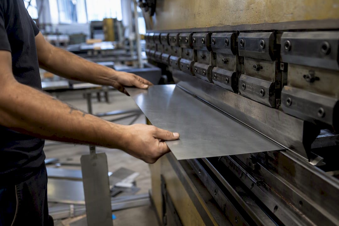
Pressure class governs gauge thickness and stiffening requirements more than any other single variable. A low-pressure plenum (up to 2 inches water gauge) can typically run lighter gauge with standard SMACNA reinforcement spacing, while medium-pressure applications demand heavier gauge and tighter reinforcement intervals to prevent oil-canning and joint failure under sustained pressure cycling.
Sealing and joint practice matters as much as gauge selection. SMACNA Class 1 sealing on transverse joints and longitudinal seams, applied with mastic rather than tape alone, is the baseline for any plenum expected to hold design static pressure without measurable leakage. Gasketed flange connections at access points and transitions cut leakage further and make future disassembly for service far cleaner than a fully welded or riveted joint.
When you brief a fabricator on a plenum order, hand over more than a CFM number:
- Full dimensions including insulation liner allowance, not just the free area calculation
- Pressure class and required SMACNA sealing class
- Access door locations and sizes, sized to fit a technician with tools, not just a hand
- Service clearance requirements around the finished plenum for future maintenance
- Fabrication tolerances, typically plus or minus 1/8 inch on critical dimensions for factory-built sections
Acoustics and performance: velocity, lining, and noise control
Velocity and noise move together almost linearly in plenum design, which is exactly why the 500 FPM return-side ceiling means something more than a compliance checkbox. Above roughly 600 to 700 FPM in an unlined plenum, air turbulence at joints, takeoffs, and transitions starts generating broadband noise that carries directly into occupied space through the ceiling cavity or supply diffusers.
Practical noise criteria for office and commercial space typically target NC-35 to NC-40, and staying under the recommended velocity ranges is the single most effective and least expensive way to hit that target. Once a plenum design pushes past those velocities for space or budget reasons, three mitigation tools do most of the work:
- Acoustic lining: 1-inch fibrous duct liner absorbs high-frequency turbulence noise inside the plenum before it reaches an occupied space, though it does eat into free cross-sectional area as noted earlier
- Turning vanes: installed at any 90-degree transition, turning vanes prevent the sharp velocity spikes and eddy currents that generate the loudest broadband noise in a plenum system
- Gradual transitions: any change in cross-section, whether a reduction or an expansion, should transition over a length at least 2.5 times the difference in dimension rather than stepping abruptly
- Attenuators: where none of the above fully resolves a noise complaint, a discrete duct silencer placed just upstream of a noise-sensitive space handles the remainder
The rectangular plenum chamber study backs this up with flow modelling: low, uniform cross-sectional velocity consistently correlates with lower pressure loss and more even distribution, which is the acoustic and the aerodynamic case for staying conservative on velocity arriving at the same conclusion from different directions.
Field acceptance for acoustics and balance should include a sound level reading at representative diffusers under normal operating conditions, plus a static pressure reading at the plenum inlet and outlet to confirm the design pressure drop matches what was calculated on paper.
Code and standards for HVAC plenum design
Every plenum specification should point back to a small, specific set of standards rather than a vague reference to “code.” SMACNA’s HVAC Duct Construction Standards governs gauge, reinforcement, and sealing class. ASHRAE’s fundamentals guidance governs pressure and flow design principles, including the return-air transfer sizing and positive-pressure guidance that the ASHRAE Journal architectural plenum analysis expands on in detail.
Where a ceiling cavity carries both return air and low-voltage cabling, CAN/ULC-S102 surface burning characteristics and plenum-rated cable requirements come into play, and they’re not optional in most jurisdictions once cable runs through the same airspace as return air. Confirm the exact requirement with the authority having jurisdiction before finalizing a ceiling cavity plenum design, since local amendments to the National Building Code vary by province and municipality.
Architectural plenums are commonly restricted or prohibited outright in several occupancy types:
- Healthcare facilities: infection control and pressure relationship requirements generally rule out ceiling cavity returns in patient care areas
- Exposed combustible construction: wood-frame ceiling cavities without adequate fire separation typically can’t serve as return air plenums under most code interpretations
- High-rise assembly occupancies: smoke control requirements often mandate ducted returns to maintain predictable smoke management during an alarm event
A short compliance checklist for specifications should confirm: plenum-rated cable and surface ratings where applicable, fire separation integrity at every penetration, sealing class matched to pressure class, and a documented AHJ consultation on file before construction begins rather than after an inspector flags it.
Installation, commissioning and testing checklist for plenums
A well-designed plenum still fails if the field crew doesn’t seal, test, and balance it correctly. Build the commissioning sequence into the specification, not as an afterthought.
- Seal every joint and seam to the specified SMACNA class using mastic on transverse joints and longitudinal seams before insulation goes on. Duct sealing is one of the most cost-effective efficiency measures available, and it applies just as much to plenums as branch ductwork.
- Leak test critical sections where the specification calls for it, particularly on medium-pressure plenums or any application where leakage directly affects a measured performance guarantee.
- Label every access panel with the zone or system it serves, so a technician five years from now doesn’t need to open three panels to find the right one.
- Verify static pressure at the plenum inlet against design values before proceeding to branch balancing; a plenum reading outside design tolerance means something upstream needs attention before TAB continues downstream.
- Balance branch by branch, working from the plenum outward, confirming each register or diffuser delivers its scheduled CFM within the accepted tolerance, typically plus or minus 10%.
- Document final readings in the TAB report, including plenum static pressure, so future service calls have a baseline to compare against.
Pro Tip: Photograph every sealed joint and labelled access panel before the ceiling goes up. It costs nothing on site and saves hours of guesswork the next time someone needs to trace a leak or locate a damper.
Ongoing inspection intervals matter too. A ceiling cavity plenum should get a visual check for moisture staining or dust accumulation at least annually, since both point to a pressure imbalance or a sealing failure that’s been quietly running since installation.
Common problems and troubleshooting for HVAC plenums
Most plenum service calls trace back to one of three root causes: an airflow imbalance, a sealing failure, or a geometry problem that was baked in at design time. Uneven temperatures between zones on the same system usually point to a plenum sized too small for total CFM, or takeoffs placed too close together fighting for the same air. Noisy registers, especially a persistent rushing sound, often mean velocity somewhere upstream, frequently right at the plenum, is running above the range this guide recommends.
Condensation on ceiling tiles or grille faces near a return path is a warning sign specific to architectural plenums: a negatively pressurized cavity is pulling in humid air from outside the conditioned envelope, exactly the risk the ASHRAE Journal analysis flags. ACHR News reporting on ductwork problems confirms these airflow and pressure issues are among the most common service complaints technicians encounter in the field.
Short-term fixes include adding a transfer boot to relieve pressure, rebalancing dampers, or adding a damper where none existed. But if the symptom returns within a season, the geometry needs to change, not the balancing. Preventing repeat calls starts at the specification stage: correct velocity targets, adequate takeoff spacing, and sealing verified before the ceiling closes up.
Manara Corp: how a fabricator designs and supplies custom plenums and ductwork
Once a plenum design is finalized on paper, someone has to build it to the tolerances the drawing promises. Manaracorp fabricates custom rectangular and round/spiral ductwork, transitions, and fittings in-shop using CNC laser cutting, sheet bending and rolling, profile rolling, and welding in steel, stainless steel, aluminum, and copper, then installs locally across Greater Montreal.
To get an accurate shop order, provide finished dimensions including any insulation liner allowance, the required SMACNA sealing class, access door locations, and a note on pressure class. Manaracorp works from architect and mechanical engineer drawings directly, and can also advise on transition geometry or stiffening where a fabrication detail isn’t fully resolved on the drawing set.
- Custom fittings and transitions built to specified radii and gauge
- Curved or radiused panel sections through in-house sheet bending and rolling
- Coordination with contractors on-site for fit and installation, not just shop delivery
Thermal performance and insulation impact on plenum design
Insulation choice affects plenum design in ways that go beyond simple heat loss control. Adding internal duct liner for acoustic control, discussed earlier, reduces free cross-sectional area and therefore raises velocity unless you’ve accounted for it in the initial sizing. External wrap insulation avoids that problem since it sits outside the sheet metal shell, preserving the calculated free area, but it adds to the overall footprint the plenum needs in a tight ceiling cavity or mechanical room.
Thermal performance matters most where a plenum runs through unconditioned space, an attic, or a shell wall condition, where uninsulated sheet metal loses conditioned air temperature to the surrounding environment before it ever reaches a diffuser. That loss shows up as reduced delivered capacity at the register, even though the air handler is producing exactly what the schedule calls for.
Condensation risk ties directly into insulation choice as well. Any plenum surface running colder than the surrounding dew point, common on cooling-season supply plenums passing through humid, unconditioned spaces, needs a vapour barrier on the insulation’s warm side to prevent moisture migration into the insulation itself. Skipping the vapour barrier on a cold supply plenum is one of the more common causes of wet insulation and eventual corrosion discovered years after installation, long after the original installer has moved on to other work.
Fire safety and smoke control measures specific to plenums
Ceiling cavity plenums occupy a unique position in fire and life safety design because they double as both an air path and, often, a cable pathway. That dual role is exactly why CAN/ULC-S102 surface burning characteristics and plenum-rated cable requirements exist: a plenum full of standard PVC-jacketed cable burns and produces smoke very differently than one wired with plenum-rated cable, and the authority having jurisdiction will check for this during inspection.
Fire separation integrity at every penetration through a plenum ceiling, whether for structural elements, piping, or cabling, needs to match the fire rating of the assembly it passes through. A ceiling cavity plenum that crosses a fire-rated corridor separation without properly fire-stopped penetrations defeats the purpose of that separation entirely, regardless of how well the plenum itself performs aerodynamically.
Smoke control takes on added weight in high-rise and assembly occupancies, where code often mandates a fully ducted return specifically so smoke dampers can isolate a zone during an alarm event. An open architectural plenum makes that kind of zone isolation far harder to achieve reliably, which is a major reason these occupancies frequently default to ducted returns even where energy codes would otherwise favour the architectural plenum’s lower fan energy.
Integration of plenums with other HVAC components
A plenum never operates in isolation. It sits directly downstream of the air handler or filter bank on the supply side, and directly upstream of the return grille or filter rack on the return side, and both connections need to be sized as carefully as the plenum itself.
Filter placement affects plenum sizing in a way that’s easy to overlook: a filter rack immediately upstream of a supply plenum needs enough straight duct or plenum length before the first takeoff to let air velocity even out after passing through the filter media, or the takeoffs closest to the filter bank will pull disproportionate airflow. A rough guideline is at least one and a half plenum widths of straight run before the first branch.
Air handler discharge connections deserve the same attention. A plenum bolted directly to an air handler discharge with no transition section inherits whatever turbulence the fan produces at that connection point, which is exactly the kind of condition turning vanes and gradual transitions are meant to resolve. Coordinate plenum dimensions with the air handler manufacturer’s recommended discharge connection detail rather than assuming a straight bolt-up will perform the same as the manufacturer’s tested configuration.
Maintenance access and cleaning considerations in plenum design
Every plenum eventually needs a technician inside it, whether for a leak trace, a filter change on an integrated component, or a routine dust and debris inspection. Access door placement decided at the design stage, not added as an afterthought during commissioning, is what makes that work possible without cutting new openings in finished sheet metal.
Size access doors for a technician with tools, not just a hand and a flashlight. A minimum of 14 by 14 inches is common, though larger plenums serving healthcare or high-occupancy spaces often warrant bigger openings given the more frequent inspection cycles those occupancies require. Space access points no further apart than roughly every 20 feet along a long extended plenum, so no single inspection requires an unreasonable reach inside the ductwork.
Dust accumulation and biological growth risk both climb in plenums with rough interior seams, exposed fibrous insulation, or standing moisture from a sealing failure. Specifying smooth interior surfaces, properly sealed liner edges, and adequate slope on any horizontal plenum section to prevent condensate pooling all reduce the frequency and severity of the cleaning that eventually has to happen. Building maintenance access into the original layout, rather than treating it as a problem for the service technician to solve later, is one of the cheapest decisions on the entire drawing set.
What this guide gets right that most plenum advice misses
Most plenum guidance online treats velocity targets as the whole story and stops there. The research tells a more complete story: geometry, specifically sectional width and height relative to length, drives flow uniformity as much as the velocity number itself does. Two plenums hitting identical FPM targets can perform completely differently depending on whether that velocity comes from a shallow, wide box or a narrow, tall one.
The conventional advice also underplays the architectural plenum’s condensation risk. Fan energy savings of 20% to 30% sound compelling on paper, and they’re real, but they’re conditional on maintaining positive pressure and sealing the cavity properly. Skip that part and you’re trading a fan energy line item for a mould remediation invoice a few years down the road.
If there’s one priority for a working designer to take from this, it’s sequencing: nail the velocity and area calculation first, then solve layout and takeoff spacing, then let materials and sealing class follow from the pressure class those first two decisions established. Designers who reverse that order, picking gauge and sealing class before confirming velocity, tend to end up retrofitting acoustic lining or stiffening after the fact, which costs more than getting it right on the first drawing.
— Ash
Get custom plenums and ductwork fabricated locally in Montreal
A well-sized plenum drawing is only as good as the shop that builds it to tolerance, and that’s where Manaracorp fits into the process you’ve just read through. Rather than sending a shop order to a distant supplier and hoping the transitions and stiffening match your specification, Manaracorp fabricates rectangular and round/spiral ductwork, fittings, and custom transitions in-shop in Lachine and installs it locally across Greater Montreal, including the West Island, Laval, and the South Shore.

That local fabrication model means the same team cutting your plenum sections with CNC laser equipment can also walk the mechanical room with you before final dimensions get locked in, something a remote supplier simply can’t offer. Whether you’re specifying a reducing plenum with multiple transition pieces or a straightforward extended plenum with staggered takeoffs, Manaracorp’s sheet bending and rolling and welding capabilities cover steel, stainless steel, aluminum, and copper in one shop.
If you have a plenum layout ready for fabrication, or you’re still working through sizing and want a second set of eyes on constructability, reach out to Manaracorp with your drawings and start the conversation on a custom ductwork shop order.
Sources
- Ashrae
- Flow characteristics and structural parametric optimisation design of rectangular plenum chambers for HVAC systems – ScienceDirect
- Askhvac
FAQ
What Is the 2-Foot Rule for Ductwork?
The 2-foot rule generally refers to keeping supply diffusers and return grilles at least 2 feet from walls, corners, or obstructions so airflow can develop properly, rather than a rule specific to plenum sizing itself.
What Is the $5,000 Rule for HVAC Systems?
There’s no established engineering standard called the “$5,000 rule” tied to plenum or HVAC design. It typically shows up in consumer contexts about repair-versus-replace cost thresholds, not in technical plenum specification, so treat any claim tying it to duct design with caution.
What Are the Common Problems With Plenums in HVAC Systems?
The most frequent issues are airflow imbalance from undersized cross-section or poorly spaced takeoffs, excessive noise from velocity above 500 to 700 FPM, and condensation risk in negatively pressurized architectural plenums, as documented in the ASHRAE Journal analysis of ceiling cavity returns.
What Is a Plenum in HVAC?
A plenum is an air distribution chamber, either a sheet metal box or a ceiling cavity, that connects the air handler to branch ductwork on the supply side or collects air from the space back to the return on the other side. Supply plenums and return plenums serve opposite directions of the same airflow loop, and both need velocity and area sized to the formula covered throughout this guide.
Can Manaracorp Fabricate a Custom Plenum From My Drawings?
Yes. Manaracorp builds custom rectangular and round ductwork, fittings, and transitions to specification using CNC laser cutting, bending, and welding, then installs locally across Greater Montreal.