Design sheet metal parts around uniform wall thickness, minimum bend radii, and correct hole-to-bend spacing, and most fabrication headaches disappear before a part ever hits the shop floor. Check your K-factor against your fabricator’s tooling, keep tolerances loose except where fit or function demands otherwise, and send both a 3D model and a flat pattern with every RFQ. Fabricators can flag the rest during a quick pre-quote review.
TL;DR:
- Ensuring holes are at least 2.5 times the material thickness from bends and edges reduces distortion and improves machining accuracy.
- Using a fabricator’s actual bend deduction chart and calibrating the K-factor improves bend allowance accuracy over default software settings.
- Designing with consistent bend direction and avoiding mixing gauges in a single part saves setup time and prevents deformation issues.
- Specifying only necessary tight tolerances and relying on realistic tolerance ranges cuts inspection costs and fabrication delays.
- Sending both a 3D formed model and a flat pattern with detailed material, finish, and tolerance notes results in more accurate RFQ responses.
Table of Contents
- Quick sheet metal design rules checklist
- How does material choice affect sheet metal design?
- Getting bend radius, K-factor and springback right
- Where should holes and slots sit relative to bends?
- What tolerances should you specify on sheet metal drawings?
- Sizing hems, bend reliefs, notches and tabs correctly
- What files should you send to a sheet metal fabricator?
- Which fabrication process fits your design?
- Should prototypes and production parts use the same design?
- Manaracorp’s shop checklist for sheet metal design review
- What day-to-day habits actually save time in the shop?
- Get your sheet metal design quoted right the first time
- Sources
- FAQ
Quick sheet metal design rules checklist
Most design errors in sheet metal come down to six repeatable mistakes: features too close to a bend, inconsistent bend direction, undersized hems, mismatched K-factors, mixed material gauges, and tolerances that are tighter than the process can hold. Run through this checklist before every design freeze.
- Hole-to-edge distance: keep holes at least 2×T (material thickness) from any cut edge to avoid distortion during punching or laser cutting.
- Hole-to-bend distance: standard practice calls for a minimum multiple of the material thickness; tight-radius bends or thicker stock may require a larger spacing. The Xometry sheet metal design guide lays out the full range by feature type.
- Minimum flange length: a flange shorter than 4×T tends to deform in the brake; anything under that should be redesigned or flagged for a specific tooling discussion.
- Hem return length: closed and open hems both need roughly 4×T minimum return length to avoid cracking at the fold.
- Bend direction consistency: orient all bends the same way where the part allows it. Reversing bend direction mid-part forces a tooling flip, which adds setup time and cost on every run.
- One thickness per part: mixing gauges in a single sheet metal part is possible but rarely worth it. It usually means two separate operations and two separate setups.
Two of these deserve a second look. Flange length gets underestimated constantly because CAD models don’t warn you when a flange is too short to clear the brake’s lower die opening. And bend direction consistency is the cheapest win on this list. It costs nothing in material and saves real setup minutes on the shop floor, especially on multi-bend brackets with more than four folds.
How does material choice affect sheet metal design?
Material and thickness decide almost everything downstream: which bend radius is achievable, how much springback to expect, and whether laser cutting or punching makes more sense. Get this wrong at the concept stage and every bend allowance calculation that follows will be off.
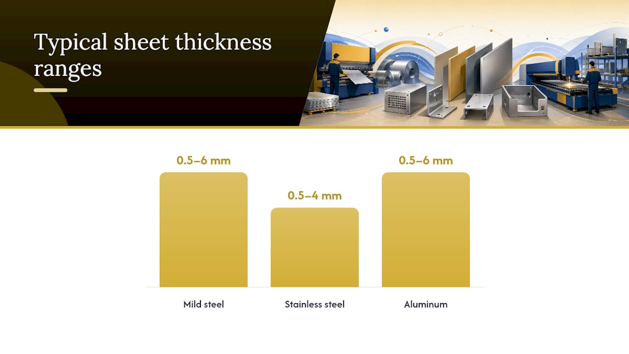
Common working thickness ranges for the three materials engineers specify most often:
- Mild steel: 0.5 mm to 6 mm for most bracket and enclosure work; above 6 mm you’re usually looking at plate fabrication rather than sheet metal forming.
- Stainless steel (304/316): 0.5 mm to 4 mm typical, with tighter minimum bend radii than mild steel of the same thickness because of its higher work-hardening rate.
- Aluminum (5052, 6061): 0.5 mm to 6 mm, but minimum inside bend radii often need to run larger than steel at the same gauge, sometimes 1.5 to 2 times the thickness, to avoid surface cracking on the outer bend face.
As a rule of thumb, minimum inside bend radius should equal material thickness for mild steel, but stainless and aluminum both push that ratio higher depending on temper and grain direction. Grain direction matters more than most designers assume: bending parallel to the grain on a tight radius is a common cause of cracked parts, and it’s one of the first things an experienced shop checks before running a job.
Bend accumulation tolerance: shop tolerance frameworks typically start at a small baseline for a single bend and allow for incremental increases relative to material thickness for each additional bend, rather than holding every formed dimension to machine-shop tolerances of ±0.002 in.
Thickness also drives which forming process makes sense. Thinner gauges (under 1.5 mm) laser cut and bend cleanly with minimal springback correction. Thicker stock needs more aggressive tonnage and larger radii, and springback becomes harder to predict without a test bend. Whatever thickness you land on, stick to standard stock gauges. A non-standard 2.3 mm sheet where 2.0 mm or 2.5 mm would do the job just as well often means a special material order and a longer lead time, for no functional benefit.
Getting bend radius, K-factor and springback right
Bend allowance calculations fail more often from a bad K-factor than from a wrong radius. CAD software defaults to a generic K-factor, usually somewhere around 0.44, regardless of your actual material or tooling setup, and that default frequently doesn’t match what a real press brake produces. Shops that specialize in sheet metal bending typically recommend calibrating K-factor in the 0.3 to 0.5 range based on the specific material, thickness, and bend radius in use, a point the Approved Sheet Metal DFM reference makes clearly for anyone still trusting the software default. Our guide to K-factor calibration walks through how to align CAD values with actual shop bend tables.
Pro Tip: Before you finalize a flat pattern, ask your fabricator for their actual bend deduction chart instead of relying on the CAD software’s built-in K-factor table. A five-minute email exchange at the design stage saves a reworked flat pattern after the first prototype bend comes back out of spec.
Springback varies by material hardness and bend angle, and no CAD tool predicts it perfectly. Stainless steel springs back more than mild steel at the same radius, which is why experienced fabricators often overbend slightly and confirm the final angle against a test piece before running a full batch. Bend sequence matters too. On multi-bend parts, the order you fold determines whether later bends clear the brake bed or collide with an already-formed flange, so sketch the sequence, not just the final geometry, before sending files out.
Where should holes and slots sit relative to bends?
Feature placement is where good designs quietly fail. A hole sitting too close to a bend line distorts when the brake forms the part, even if the flat pattern looked perfect on screen.
- Hole-to-bend minimum: 2.5×T to 6×T depending on hole diameter and bend radius; use the wider spacing on anything thicker than 3 mm or bent to a tight radius.
- Hole-to-edge minimum: 2×T from any free edge, measured from the hole edge, not its centre.
- Slot vs hole: prefer slots over closely spaced holes when you need to save material or reduce stress concentration along a cut line, but keep slot ends at least 1×T from any edge or bend.
- Feature-to-feature spacing: separate adjacent holes or slots by at least 2×T to avoid tearing the material bridge between them and to protect punch tooling life.
- Relief cuts near bends: any hole or slot that intersects a bend line needs a relief cut, sized at minimum 1×MT wide and longer than the bend radius itself, according to the Xometry design guide.
Sharp internal corners on any cutout are the other recurring problem. They concentrate stress and slow production because the shop often has to hand-finish or re-tool around them. A generous fillet radius on internal corners costs nothing in function and measurably improves yield.
Pro Tip: If a hole absolutely must sit close to a bend for functional reasons, model the relief cut explicitly in CAD rather than leaving it to the fabricator’s discretion. That one decision, documented on the drawing, prevents the most common back-and-forth email chain in sheet metal quoting.
What tolerances should you specify on sheet metal drawings?
Tighten tolerances only where fit or function genuinely requires it. Applying machinist-grade tolerances to every dimension on a formed part inflates inspection time and cost without improving the part.
Realistic tolerance bands look roughly like this:
- Flat, single-plane dimensions (laser cut, no forming): ±0.005 in is achievable and reasonable to specify.
- Single-bend dimensions: expect roughly ±0.006 in as a starting baseline, tightening only where a mating part demands it.
- Multi-bend dimensions: tolerance widens with each additional bend, adding roughly 5% of material thickness per bend to account for accumulated forming variation, a framework detailed by The Fabricator.
Shop-floor experience consistently shows that over-tolerancing non-critical dimensions is one of the most common and avoidable costs in sheet metal fabrication, according to The Fabricator’s guidance on reasonable tolerances.
Call out general tolerances in a drawing note rather than repeating them on every dimension, and reserve individual tight callouts for the two or three features that actually mate with another part or house a fastener. If a project genuinely needs tighter control, ask the fabricator for a capability statement before committing tolerances to the drawing. It’s a faster path to a realistic number than guessing from a generic chart, and it avoids a quote coming back with a note that a callout can’t be held on that equipment.
Sizing hems, bend reliefs, notches and tabs correctly
Edge treatments and small features fail more from undersizing than from bad geometry. The numbers below apply across most mild steel, stainless, and aluminum jobs, scaled to material thickness (T).
-
Open hem: minimum return length of roughly 3×T; simplest to form and the most tolerant of variation.
-
Flat hem: minimum return length of 4×T to 5×T; watch for fracture risk on harder materials or tight radii, since a flat hem folds the material back on itself almost completely.
-
Tear-drop hem: a compromise that leaves a small radius gap inside the fold, useful when a full flat hem risks cracking a stiffer alloy.
-
Relief cut width: minimum 1×MT, and the cut should run longer than the bend radius itself to fully clear the forming stress, a detail covered in Mosquera’s guide to bend reliefs.
-
Notch and tab minimum width: keep tabs no narrower than 1×T, and avoid length-to-width ratios beyond roughly 4:1 or the tab risks bending or breaking off during handling.
If a flat hem keeps failing in testing on a harder alloy, don’t fight the material. Switch to an open or tear-drop hem instead of pushing tonnage higher, which just increases the odds of a cracked edge on the production run. Our hemming design guide breaks down which hem type suits which application in more detail.
What files should you send to a sheet metal fabricator?
Fabricators quote faster and more accurately from a complete file package than from a flat DXF alone, especially on parts with more than one or two bends.
- Formed 3D model in STEP (.stp) or native CAD format (.sldprt), showing the part as it looks after bending, not just the flat blank.
- Flat pattern DXF, generated from the same model, used directly for laser or punch programming.
- Metadata note covering material and grade, thickness, the K-factor assumption used to generate the flat pattern, bend direction, any critical tolerances, finish requirements, and quantity.
- Annotated drawing (PDF) calling out any dimension that isn’t obvious from the model, particularly on parts with unusual hem types or relief cuts.
Sending the formed model alongside the flat pattern, rather than the DXF alone, is standard advice from Xometry’s design guide because it lets the shop verify your K-factor assumption matches their tooling before they cut anything. A DXF-only submission works fine for flat, unbent parts, but on anything with a fold, it forces the fabricator to guess at your bend allowance logic. Our laser cutting design rules guide covers DXF prep specifics if flat-cut parts are your main concern.
Which fabrication process fits your design?
Laser cutting suits low-volume runs and complex contours because there’s no dedicated tooling cost. Punching and stamping take over as volume climbs, since per-part cost drops fast once a die is in production.
- Laser cutting: best for prototypes, one-off parts, and complex or curved contours where cutting a punch die wouldn’t pay for itself.
- Punching/stamping: cost-effective at higher volumes, but flange geometry gets constrained by whatever tooling the shop already owns or is willing to build.
- Press brake tooling: different die widths and punch profiles limit achievable flange lengths and inside radii, so a design that looks fine in CAD can be impossible on the tooling actually available.
- Welding and joining: holes for fasteners near a weld joint need extra clearance, since heat distortion during welding can shift tolerances that were fine before assembly.
- Finishing: powder coating and plating both add measurable thickness, typically fractions of a millimetre, which matters on parts with tight-fitting mating features.
Each process shift changes what “correct” geometry looks like on the same nominal part, which is exactly why NeuronicWorks’ DFM overview treats bending and stamping as genuinely separate design problems rather than interchangeable options.
Should prototypes and production parts use the same design?
No. A prototype tolerance you’d never accept on a production run is often the right call early on, and a production geometry choice you’d never bother with for a single prototype is often the right call once volume climbs.
- Accept looser tolerances early. A prototype exists to validate fit and function, not to prove manufacturability at scale, so don’t burn budget chasing tight tolerances on a part that might still change shape next week.
- Fix tooling geometry before committing to production. Once a design is locked, dedicated die geometry for stamping or progressive dies becomes worth the investment, a trade-off SR-MFG’s design guide frames clearly against staying on a flexible laser-and-brake workflow.
- Plan nesting and material utilization for volume. A part that nests efficiently on a sheet at 500 units saves real material cost that doesn’t show up at prototype quantities of five.
- Run a production-readiness DFM review before releasing final tooling, checking that every hole, hem, and bend still matches what the chosen production process can actually hold.
Manaracorp’s shop checklist for sheet metal design review
Every RFQ that comes through Manaracorp’s shop in Lachine gets checked against the same short list before a quote goes out, because the same three or four problems show up on files far more often than anything exotic.
- File completeness: 3D model plus flat pattern, material and finish called out, critical tolerances flagged, bend direction indicated.
- Hole-to-bend spacing: the single most common fix requested. Holes modelled too close to a bend line, sometimes by just a millimetre or two, need to move before the part can form cleanly.
- Flange length: flanges under 4×T frequently need a redesign or a specific tooling conversation before quoting can even start.
- Hem type mismatch: a flat hem specified on a harder alloy where an open or tear-drop hem would form without fracture risk.
Pro Tip: Send an annotated flat pattern with a direct line to your contact for a quick design-for-manufacturability check before committing to final tolerances. A five-minute conversation at the RFQ stage routinely saves a full re-quote cycle later.
What day-to-day habits actually save time in the shop?
The fastest DFM review checks four things in order: hole-to-bend spacing, flange length, K-factor assumptions, and tolerance callouts on non-critical features. Catch a problem in that sequence and you’ve usually caught the part’s biggest risk.
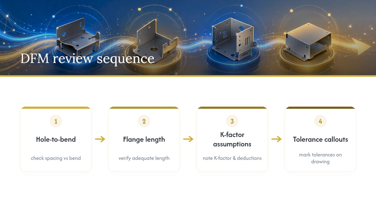
Document every assumption directly on the drawing rather than trusting it lives in someone’s head. If you assumed a K-factor of 0.42 or a specific bend deduction, write it down. It saves a confused phone call when the flat pattern comes back different from what you expected.
And if a geometry looks unusual, a hem type you haven’t used before, a bend radius near a material’s limit, call the fabricator before finalizing it. A five-minute conversation at the design stage is always cheaper than a reworked part after the first run.
— Ash
Get your sheet metal design quoted right the first time
A custom metal fabrication shop with local expertise provides a faster route to a working part than trial-and-error with a generic online quoting tool. Every RFQ gets a real review from experienced metal fabricators, not an algorithm applying a generic K-factor to your file.

Send a 3D model, a flat pattern, and your material and finish notes, and Manaracorp will flag hole-to-bend spacing issues, flange length problems, or hem type mismatches before quoting, not after the first prototype comes back wrong. The shop handles CNC laser cutting, sheet bending and rolling, profile rolling, and welding across steel, stainless, aluminum, and copper, with everything fabricated in-shop and installed locally across Greater Montreal, from the West Island to Laval and the South Shore. If your project also involves railings, stairs, or fencing, fabrication and installation services for these can be arranged through the same metal fabrication shop. Submit your files and drawing notes through the contact page and get a real DFM read on your design before you commit to a production run.
Sources
The tolerance bands, bend rules, and CAD recommendations in this guide draw on The Fabricator’s shop-floor tolerance guidance, the Xometry sheet metal design guide, Approved Sheet Metal’s DFM reference, SR-MFG’s CAD-to-production guide, and NeuronicWorks’ DFM overview. For thin-gauge material choices specifically, Signature Laser Designs’ data plate thickness guide offers a useful practical reference point.
- What sheet metal shops wish you knew: Reasonable tolerances, grain direction, and the base flange — The Fabricator
- Xometry sheet metal design guide (PDF)
- Sheet Metal Design Guide: From CAD to Production Drawings — SR-MFG
FAQ
What are the basic rules for designing sheet metal?
Keep wall thickness uniform, hold minimum bend radii near 1×T for mild steel, space holes at least 2.5×T from any bend and 2×T from any edge, and reserve tight tolerances for features that actually mate with another part.
What does “sheet metal design” mean?
Sheet metal design means engineering a part to be cut and formed from flat stock (typically laser cut or punched, then bent on a press brake) while respecting the material’s bend radius, springback, and feature spacing limits. It’s a subset of design for manufacturability (DFM) focused specifically on flat-to-formed geometry.
What is the best sheet metal design software?
Most engineers use the sheet metal environment in SolidWorks or Inventor rather than modelling parts as solids and converting them, since these tools generate flat patterns automatically once material thickness and K-factor are set correctly.
How do you shape sheet metal by hand?
Hand-forming works for simple bends on thin stock using a bench vise, hand seamer, or hand brake, but it can’t reliably hold the bend radius or angle consistency that a press brake achieves, so it’s suited to one-off prototypes rather than production parts.