Size a rectangular duct by running the equal friction method to find an equivalent round diameter for your airflow, then converting that diameter to width and height with the Huebscher relationship. Target a friction rate of 0.06 to 0.08 in.wg per 100 ft for quiet residential trunks, or up to 0.15 in.wg per 100 ft for commercial runs with more available static, and keep velocity in the 5 to 9 m/s band. Round to the nearest stock size, then re-check velocity and pressure drop before you cut metal.
TL;DR:
- The equal friction method is suitable for small residential and light commercial systems due to its speed, simplicity, and natural balancing of branch sizes.
- For larger or high-efficiency systems, it is advisable to use the T-method or a life-cycle-cost approach to optimize duct and fan expenses over the system’s lifespan.
- To size a rectangular duct, calculate the equivalent round diameter based on friction rate and convert to width and height using Huebscher’s formula, adjusting for stock sizes and constraints.
- Maintain friction rates of 0.06 to 0.08 in.wg per 100 ft for quiet residential trunks and velocity within 5 to 9 meters per second; higher static and velocity are acceptable in larger commercial mains.
- Engage fabricators early to account for material tolerances and fabrication limits, ensuring dimensions are practical and cost-effective before finalizing designs.
Table of Contents
- What is the best method for rectangular duct sizing?
- How do you calculate rectangular duct size step by step?
- What velocity and friction rate should you target?
- How much clearance does fabrication actually need?
- What should you check in a duct sizing calculator?
- Why fabricators should be in the sizing conversation early
- Get your rectangular duct sections built right the first time
- Sources
- FAQ
What is the best method for rectangular duct sizing?
Four sizing methods show up in practice, and they trade simplicity against performance in different ways.
The equal friction method holds the friction rate constant along the whole trunk. It is the usual first pass because it is fast, requires no iteration, and tends to produce a semi-self-balancing layout — branch sizes shrink naturally downstream, which cuts down on how many balancing dampers you need to install.
Static regain recalculates velocity at every branch so the pressure gained from slowing the airflow offsets friction losses further along the run. It earns its complexity on long branched mains, typically in bigger commercial or industrial layouts where a single friction rate would leave terminal boxes starved for pressure.
Velocity reduction simply steps velocity down at each junction by a fixed ratio. It is a legacy method, mostly seen where a designer wants an easy hand calculation without software.
The T-method is a life-cycle-cost optimization approach. Instead of one heuristic friction rate, it evaluates duct and fan cost together, iterating against a real fan curve and energy pricing to find the cheapest combination over the system’s service life, though this comes at the price of far more computation than a heuristic pass.
Here is the decision rule that actually holds up in the field:
- Small residential or light commercial jobs: use equal friction and move on.
- Large systems, high energy costs, or a client asking for documented efficiency: run the T-method or a comparable LCC tool once the equal friction pass gives you starting sizes.
How do you calculate rectangular duct size step by step?
Gather five inputs before you touch a formula: design airflow in CFM, run length, an allowance for fittings and elbows, the surface roughness or friction factor of your duct material, and any fixed side constraint (a joist bay height, a ceiling void, a chase width).
The workflow runs on two formulas. First, solve the standard round-duct friction equation for the diameter that delivers your target friction rate at the design airflow. Second, convert that round diameter into rectangular width and height with the Huebscher equivalent-diameter relationship:
De = 1.30 × (a × b)^0.625 / (a + b)^0.250
where De is the equivalent round diameter and a, b are the rectangular duct’s two sides in the same units.
Pro Tip: When one side is fixed by the structure, treat that side as a known and solve Huebscher for the unknown side numerically. Most practical calculators do this with a quick binary search rather than an algebraic rearrangement, since the equation doesn’t isolate cleanly.
- Set your target friction rate (say 0.08 in.wg/100 ft for a quiet residential trunk).
- Solve the round-duct friction equation for the required diameter at your design CFM.
- Plug that diameter into the Huebscher formula as De, fix one side if constrained, and solve for the other.
- Compute actual velocity (CFM ÷ cross-sectional area) and re-derive the friction loss for that exact rectangular shape.
- Round both sides to the nearest standard stock increment (usually 1 inch).
- Re-check velocity and pressure drop against your targets. If rounding pushed velocity too high, bump the constrained side up one increment.
Worked example: A 1,200 CFM trunk needs sizing at 0.08 in.wg/100 ft, with one side fixed at 12 inches by the ceiling void. Solving the friction equation gives a round equivalent diameter near 14.8 inches. Feeding De = 14.8 into Huebscher with a = 12 fixed and solving numerically for b returns roughly 16 inches. Rounded to stock, that is a 12 × 16 duct. Cross-sectional area works out to 133.3 in², giving a velocity of about 1,297 fpm (6.6 m/s) — inside the general HVAC band — and a recalculated friction rate close to the 0.08 target once you account for the rounding.
Add the fittings allowance from the ASHRAE Duct Fitting Database before you finalize static pressure for the run — elbows and transitions on a 12 × 16 section are not free, and skipping that loss coefficient is one of the more common ways a sized duct underperforms once installed.
What velocity and friction rate should you target?
Match your friction rate to what the space and the fan can tolerate, not to a single number you memorized once.
- Quiet residential trunks: 0.06 to 0.08 in.wg per 100 ft, keeping velocity near the low end of the range.
- General HVAC runs: friction climbs toward 0.10 to 0.12 in.wg per 100 ft with more available static.
- Commercial mains with higher static budgets: 0.12 to 0.15 in.wg per 100 ft is common where noise is less of a concern.
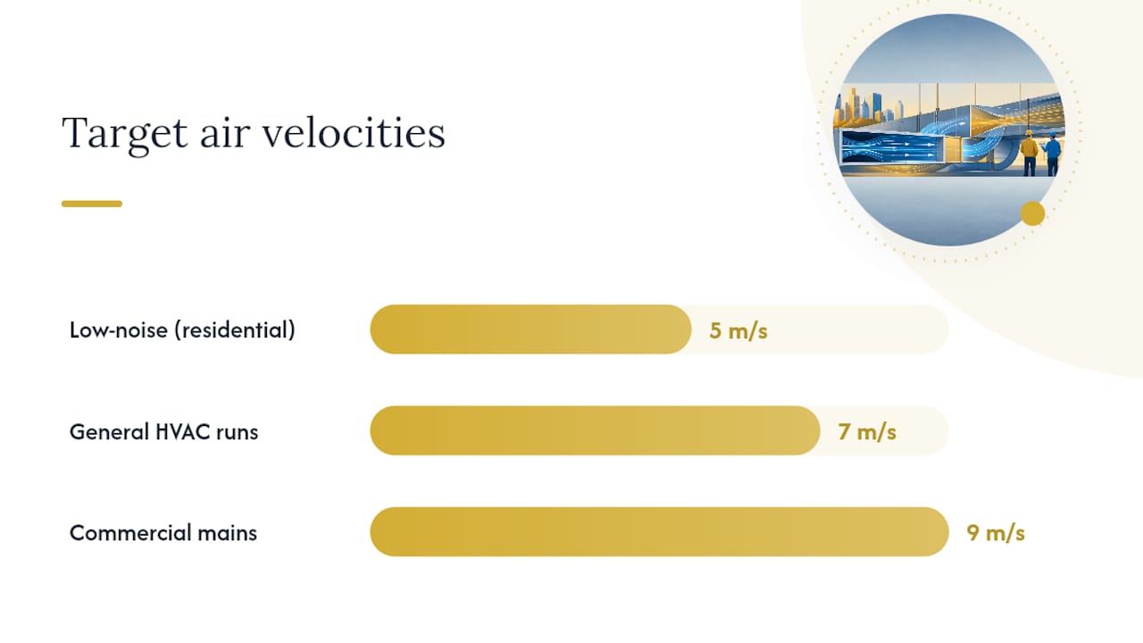
Velocity bands follow a similar logic: roughly 5 m/s (985 fpm) for low-noise applications, 7 m/s (1,378 fpm) for general HVAC work, and up to 9 m/s (1,772 fpm) on larger mains where noise matters less and space is tight. Push friction and velocity too high and you shrink the duct, but you also shrink your fan’s operating margin and raise operating cost over the system’s life — the T-method exists precisely to quantify that trade-off.
Pro Tip: Before locking a friction rate, check how much static the fan actually has to spend. A rate that looks efficient on paper is worthless if the fan curve can’t deliver it across every branch.
How much clearance does fabrication actually need?
SMACNA-derived shop rules govern how far you can push a rectangular cross-section before it becomes a fabrication or performance problem.
- Keep the aspect ratio (height to width) at 2:1 to 2.5:1 where possible; anything past 4:1 needs reinforcement and should be avoided if there is any layout flexibility.
- Larger panels require cross-breaking or beading to prevent oil-canning, which adds shop time and cost.
- Minimum gauge and permitted seam types are set by SMACNA tables tied to duct dimension and pressure class, not by preference.
- Wide, flat sections often cost more to build well than two narrower sections joined with a transition, once bracing is factored in.
Talk to your fabricator before the drawings are final, especially around tight joist bays or awkward transitions — a five-minute conversation about hemming and bend allowances at the sketch stage avoids a much longer one after material is ordered.
What should you check in a duct sizing calculator?
Prioritize four inputs when you sit down with a calculator: airflow in CFM, target friction rate, run length, and any fixed side constraint. Add a fittings allowance so the tool’s output reflects real losses, not just straight-duct friction.
- Confirm the equivalent diameter the tool computed matches your hand check.
- Verify the resulting width and height, then confirm velocity and pressure drop per unit length both sit inside your target bands.
- Re-run the check after rounding to stock dimensions. Rounding shifts velocity slightly every time, and occasionally enough to matter.
- Save the calculator’s settings and outputs alongside your plenum layout so procurement and the fabrication shop are working from the same numbers, not a rounded summary.
Why fabricators should be in the sizing conversation early
Shop tolerances, minimum producible sizes, and current lead times all shape what a “clean” calculated size actually costs to build. Bringing a fabricator in while dimensions are still flexible, rather than after drawings are stamped, tends to cut material waste and simplifies the fittings that make or break an on-site install. It is a coordination step, not a formality.
— Ash
Get your rectangular duct sections built right the first time
Formulas get you to the right numbers; a shop that understands stock sizes, gauge limits, and bracing gets those numbers into metal without rework. Manara Corp. fabricates rectangular sections, transitions, and fittings in-house in Lachine and installs them on-site across Greater Montreal, from the island to Laval, the South Shore, and the West Island.

Our shop runs CNC laser cutting, sheet bending and rolling, profile rolling, and welding across steel, stainless steel, aluminum, and copper, so a fixed-side constraint or an awkward transition gets solved in the drawing stage instead of on the ladder. We also coordinate directly with post-construction cleaning crews like Sparkle Pro to keep handoffs smooth once installation wraps. If you have a set of calculated dimensions or a rough sketch, send us your drawings or RFI through our contact page and we will confirm fabricability, gauge, and bracing before you commit to stock sizes.
Sources
- Equal friction method — Engineering Toolbox
- Chapter 34: Duct design — ASHRAE fundamentals references
- Ductwork fabrication guidelines — Dartmouth construction guidelines (SMACNA references)
FAQ
What is the standard size of rectangular ducts?
There is no single standard size. Rectangular duct dimensions come from calculating an equivalent round diameter for your airflow and target friction rate, then converting to width and height with the Huebscher relationship and rounding to the nearest 1 inch stock increment.
What is the 2 foot rule for ductwork?
This isn’t a formal sizing rule in SMACNA or ASHRAE references; it is shop shorthand some contractors use for spacing supports or reinforcement on long straight runs. Follow your fabricator’s bracing schedule and the SMACNA-derived gauge and reinforcement tables instead of a rule of thumb.
How do you calculate duct sizing?
Pick a target friction rate for the application, solve the round-duct friction equation for the diameter that delivers it at your design CFM, then apply the Huebscher formula to convert that diameter into a rectangular width and height, checking velocity and pressure drop afterward.
What is the formula for calculating rectangular duct size?
The core formula is Huebscher’s equivalent diameter relationship: De = 1.30 × (a × b)^0.625 / (a + b)^0.250, where De is the round duct diameter with equal friction performance and a, b are the rectangular sides you are solving for.
What aspect ratio should a rectangular duct have?
Keep the height to width ratio between 2:1 and 2.5:1 where the layout allows it. Ratios beyond 4:1 need added reinforcement per SMACNA fabrication guidance and generally cost more to build well.