Size every feature relative to material thickness (T) and most laser cutting problems disappear before they start. That’s the single rule underneath everything else in this guide. The working defaults: minimum hole diameter ≥ T, minimum wall thickness ≥ 1.5T, minimum feature-to-edge clearance ≥ 1T, closed vector loops only, files delivered as DXF or STEP, and a scrap coupon run before full production on anything with tight fits. Ask for a design-for-manufacturability (DFM) review whenever you plan to break one of these numbers.
Before you export anything, run this three-step check:
- Scale check: every hole, slot, and wall meets the T-based minimums above.
- File check: vectors are closed, text is outlined, and you’re sending DXF or STEP, not a PDF with dimension lines baked in.
- Fit check: if two parts interlock or a hole needs to hold a bearing, you’ve flagged the tolerance and requested a scrap coupon.
The sections below cover the exceptions, the material-specific limits, and the bend rules that don’t fit in a three-line checklist.
Key Takeaways
Designing for laser cutting comes down to sizing every feature as a multiple of material thickness (T) and sending clean, closed-vector files with the right formats attached.
| Point | Details |
|---|---|
| Use T as your unit | Size holes ≥ 1T, walls and slots ≥ 1.5T, and edge clearance ≥ 1T for any material or gauge. |
| Draw to nominal | Let the fabricator’s CAM software handle kerf compensation instead of pre-adjusting your own dimensions. |
| Respect bend clearances | Keep holes at least 2T + R from any bend line to avoid distortion during forming. |
| Reduce pierce count | Combine adjacent holes into slots and simplify outlines to cut cost and cycle time. |
| Validate before full production | Run a scrap coupon and review a 3D preview before committing to a full run. |
Table of Contents
- Why laser cutting design rules exist: kerf, HAZ, and physical limits
- What file formats and prep steps do laser cutters need?
- What are the minimum feature sizes for laser cutting?
- Which materials work best for laser cutting, and which should you avoid?
- What tolerance can you expect from laser cutting?
- How do you design laser-cut parts for bending?
- How can you reduce laser cutting cost without hurting the design?
- What safety issues should you flag before laser cutting?
- How do you validate a laser cutting design before full production?
- What should you send when requesting a laser cutting quote?
- How Manara Corp applies these rules on the shop floor
- What the rules get wrong, and what to fix first
- Sources
- FAQ
Why laser cutting design rules exist: kerf, HAZ, and physical limits
A laser doesn’t cut a mathematically perfect line. It vaporizes a path of material, and that path has width. That width is kerf, and it’s usually somewhere in the range of 0.05 mm to 0.5 mm depending on material and machine. Around that cut line sits a heat-affected zone (HAZ), a narrow band where the material’s grain structure and hardness shift slightly from the heat, even though it never melts.
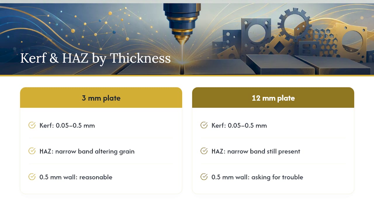
Both effects matter most at small scales. A hole drawn at 1 mm in a 3 mm-thick plate doesn’t just risk closing up from kerf. It sits inside a zone where heat has already altered the metal around it, so the edge quality and roundness suffer. Thin webs between two cutouts face a similar problem: the HAZ from both edges can overlap, weakening or warping a wall that looked fine on screen.
This is why every rule in this guide is expressed as a multiple of material thickness rather than a fixed millimetre value. A 0.5 mm minimum wall makes sense in 3 mm steel. It’s asking for trouble in 12 mm plate. When your design pushes past these ratios, expect either a DFM conversation with your fabricator or a plan for secondary machining, like drilling out a hole the laser can’t cleanly produce on its own.
What file formats and prep steps do laser cutters need?
Your file format choice depends on what happens to the part after it leaves the laser bed. Flat parts that stay flat want DXF or DWG. Anything getting bent afterward benefits from STEP or IGES, since those formats carry the 3D geometry a programmer needs to unfold the part correctly and place bend lines. SVG and PDF work for some shops’ upload portals, but raster formats like JPG or PNG should be reserved for engraving artwork, never for cut geometry, because a laser cutter needs vector paths, not pixels.
A clean handoff follows a short sequence:
- Convert all text to outlines. A font that isn’t installed on the shop’s system turns into garbage geometry or gets skipped entirely.
- Use hairline stroke weight for every cutting path. Thick strokes can get interpreted as double lines or fills, confusing the CAM software.
- Strip out borders, dimension lines, and scale notes. Send only the profile that needs to be cut. Anything else risks getting interpreted as a cut line, which is exactly the kind of error a fabricator catches only after the sheet is already in the machine, according to Ponoko’s file-prep guidance.
- Colour-code cut versus engrave operations. Most shops read layer colour to separate the two, so red for cut and blue for engrave (or whatever convention your fabricator specifies) avoids a part coming back engraved where it should have been cut through.
Attach material type, thickness, quantity, finish, and any critical tolerances directly with the file upload rather than in a follow-up email. That single step is usually what separates a same-day quote from a three-message back-and-forth.
Pro Tip: If your CAD software exports overlapping duplicate lines along a shared edge, the laser may retrace that path twice, doubling cut time and sometimes burning a wider kerf into that one edge. Run a duplicate-line check before export, especially after copying and mirroring geometry.
What are the minimum feature sizes for laser cutting?
Material thickness (T) is the unit that makes these rules portable. A shop cutting 1 mm aluminum and 10 mm steel on the same day can’t work from a single millimetre table, but a T-based rule scales automatically, and that’s exactly why shops that publish DFM guides frame every clearance as a multiple of T rather than a fixed number.
The core numbers, as rule-of-thumb starting points:
- Minimum hole diameter: ≥ 1T. Holes smaller than the material’s thickness generally need a secondary drilling operation, because the laser struggles to hold roundness and a clean edge at that ratio.
- Minimum wall thickness: ≥ 1.5T. Thinner walls between two cutouts risk warping from heat buildup or snapping during handling.
- Minimum slot width: ≥ 1.5T, following the same logic as wall thickness.
- Minimum feature-to-edge clearance: ≥ 1T. Keep any hole or slot at least one thickness away from an outside edge to avoid tearing or blow-through at the perimeter.
Here’s how those ratios translate into real numbers across common gauges:
These are starting defaults, not hard laws of physics. A few exceptions come up often enough to plan for:
- Micro-tabs and tiny standoffs below the minimum wall rule sometimes survive in a nest if they’re supported on multiple sides rather than cantilevered, but treat that as a case for a DFM conversation, not a default assumption.
- Undersized holes for pins or dowels usually get flagged for secondary drilling rather than rejected outright. Tell your fabricator up front which holes need a reamed or drilled finish so they can quote it correctly the first time.
- Dense micro-perforation patterns (think decorative screens or ventilation grilles) push nesting software and cycle time hard. If you’re designing one, expect a conversation about pierce count before the quote comes back.
If a part genuinely needs a feature smaller than these ratios allow, that’s the moment to ask for a formal DFM review rather than guessing and hoping the first article comes out clean.
Which materials work best for laser cutting, and which should you avoid?
Mild steel, stainless steel, aluminum, and copper are the workhorses of CNC laser cutting, and most shops handle them comfortably from roughly 0.5 mm sheet up through 25 mm plate, though thicker gauges slow the cut and may need a higher-power fibre laser to stay economical. Acrylic cuts cleanly on CO2 machines from 1.5 mm up to about 20 mm, with a distinctive flame-polished edge that needs no secondary finishing. Plywood and MDF also cut well on CO2 systems, typically in the 3 mm to 18 mm range, though wood’s natural grain can cause minor edge charring that some projects need sanded afterward.
A short list of materials to keep off the cutting bed entirely:
- PVC and other chlorine-containing plastics. Cutting them releases chlorine gas, which is toxic and corrosive to both people and machine optics.
- Certain fibreglass and carbon-fibre composites. These can release hazardous particulates and resin fumes, and the fibres themselves often don’t cut cleanly.
- Galvanized steel without ventilation planning. The zinc coating vaporizes into zinc oxide fumes, which isn’t a reason to avoid galvanized steel altogether, but it does mean the shop needs proper extraction in place before the job runs.
- HDPE and polystyrene foam. Both tend to melt rather than vaporize cleanly, leaving a gummy, uneven edge instead of a cut line.
Assist gas choice also shapes your finished edge. Oxygen assist speeds up cutting mild steel but leaves an oxidized, darker edge that may need cleaning before painting or welding. Nitrogen assist costs more but leaves a bright, oxide-free edge, which matters for stainless steel parts headed straight into a visible application. If your project has a specific finish requirement, raise it with your fabricator before the job is scheduled, not after the parts arrive.
What tolerance can you expect from laser cutting?
Kerf isn’t a fixed number. It shifts with material type, thickness, and the specific machine cutting it, generally landing somewhere between 0.05 mm and 0.5 mm for typical sheet metal jobs. That range matters less than you’d think for day-to-day design work, because kerf compensation is normally handled inside the shop’s CAM software, not by the designer.
The practical rule: draw your parts to nominal, finished dimensions. Don’t try to pre-compensate for kerf yourself unless your fabricator specifically asks you to, since that’s a step most shops build into their own programming, and duplicating it on your end can introduce more error than it solves.
Most shops can hold general profile tolerances in the range of ±0.1 mm to ±0.25 mm on sheet metal under about 6 mm thick, tightening or loosening depending on material and part geometry. That’s tight enough for the overwhelming majority of brackets, panels, and enclosures. When a project needs true precision fits, bearing bores, press-fit pins, mating assemblies, plan for a secondary machining pass like reaming or CNC milling rather than expecting the laser alone to deliver it.
If your design includes interlocking tabs, snap-fit joints, or anything where two laser-cut parts need to slide together with a specific clearance, say so explicitly when you submit the file. That’s the one scenario where you should ask for a specific kerf offset rather than trusting the shop’s default compensation, since interlocking geometry is far less forgiving of a few hundredths of a millimetre than a mounting hole is.
How do you design laser-cut parts for bending?
A flat pattern that ignores bend mechanics is the fastest way to end up with cracked corners or a part that springs back out of tolerance. Bend radius, flange length, and hole placement all need to respect the material’s behaviour under load, and each material bends differently.
- Minimum inside bend radius runs about 1T for mild steel and closer to 1.5T for stainless steel, since stainless work-hardens faster and cracks more easily at a tight radius. Aluminum sits somewhere in between depending on alloy and temper, so check with your fabricator on anything other than the most common 5052 or 6061 grades.
- Minimum flange length generally needs to be at least four times the material thickness plus the bend radius, giving the brake enough material to grip without the flange deforming or slipping during the press.
- Hole-to-bend clearance follows the formula 2T + R, meaning any hole or slot needs to sit at least twice the thickness plus the bend radius away from the bend line. Closer than that, and the hole distorts or the bend line shifts unpredictably.
- Bend reliefs (small notches cut at the ends of a bend line where it meets a part edge) prevent tearing at that corner. A relief roughly equal to the material thickness in both width and depth is a reasonable default, adjusted for material and bend angle.
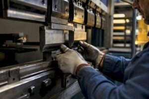
If your part combines laser cutting with a press brake step, it’s worth designing the flat pattern and the bend sequence together rather than treating them as separate stages, since a bend that works in isolation can conflict with a hole placed for an entirely different reason. Manara Corp’s sheet bending and rolling work regularly starts from laser-cut blanks designed with exactly these clearances in mind.
How can you reduce laser cutting cost without hurting the design?
Pierce count drives cost more than most designers expect. Every time the laser has to stop, pierce a new starting point, and begin cutting again, it adds cycle time, and pierce count, part complexity, and nesting efficiency together make up the bulk of a laser job’s cost structure.
A few design habits keep that number down:
- Combine small adjacent holes into a single slot where the function allows it. One pierce instead of three or four adds up fast across a production run.
- Simplify outline complexity. Sharp internal corners and tight zigzag profiles slow the cutting head down; smoother transitions let it maintain speed.
- Design to standard stock sheet sizes where possible, since a part that nests efficiently on a standard sheet wastes less material and leaves the fabricator less scrap to account for in the quote.
- Don’t over-spec thickness “just in case.” Thicker material cuts slower and costs more per part, and it’s not always the safer choice. A 3 mm part that needs the rigidity of 6 mm is a real trade-off worth discussing, not a default.
Pro Tip: If you’re cutting a batch of similar parts, group them into a single nested file rather than submitting separate files for each. Most fabricators quote nested jobs more efficiently, and it gives their programmer full control over sheet utilization.
What safety issues should you flag before laser cutting?
Coatings and finishes matter as much as the base metal. Painted, galvanized, or otherwise coated stock can release toxic fumes when the laser burns through the surface layer, so flag any coating in your quote request rather than assuming it’s obvious from the file. Some finishes, particularly certain powder coats or chrome plating, may get refused outright or require special ventilation handling that not every shop has set up.
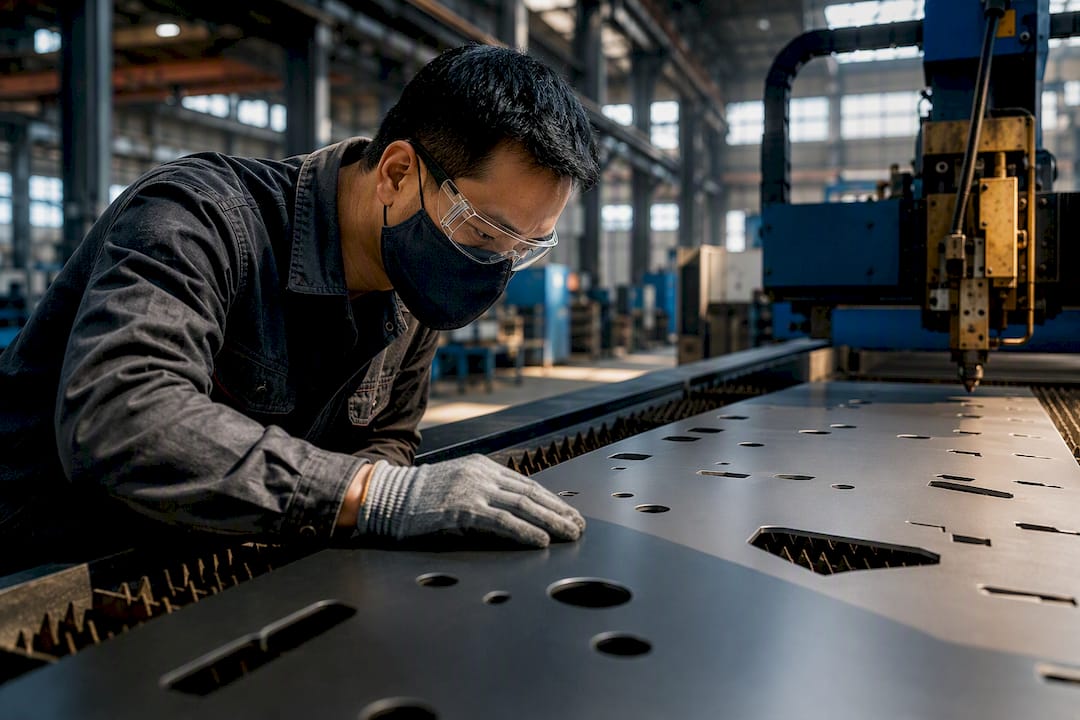
Assist gas, bed type, and micro-tab placement all interact in ways that aren’t always visible from the CAD file alone. A slatted bed handles thin sheet differently than a honeycomb bed, and micro-tabs (the small uncut points that hold a part in the sheet during cutting) need to be placed where they won’t interfere with a critical edge. These are worth a quick conversation with your fabricator rather than a guess.
How do you validate a laser cutting design before full production?
Run a scrap coupon first. This is a small test cut containing the job’s smallest holes, thinnest walls, and any interlocking features, and it’s the cheapest insurance available against a full production run coming back wrong.
- Cut a scrap coupon with the job’s tightest tolerances represented in miniature, checking hole fit, kerf width, and edge quality before committing material to the full run.
- Review the fabricator’s 3D preview or proof render. This step catches stencil-island problems (where a letter like “O” loses its centre) and misaligned nesting before the sheet ever hits the bed.
- Request a photographed first article with a dimensional report for any part with a critical fit, giving you a documented check against your drawing before the rest of the run proceeds.
None of this adds meaningful time to a project, and it consistently costs less than a rejected batch.
What should you send when requesting a laser cutting quote?
Speed up your quote by sending everything at once instead of in pieces:
- DXF for flat profiles, plus STEP if the part gets bent afterward.
- Material type and thickness, stated explicitly rather than assumed from the file.
- Quantity, since pricing per part shifts significantly with batch size.
- Finish requirements (mill finish, powder coat, deburred edges) and any critical tolerances called out directly on the file or in the notes.
- Labelled files and parts, especially for multi-part orders, so nesting and assembly don’t get mixed up.
- A note requesting DFM review if any feature pushes close to the minimum size rules covered above, or if bends, tabs, or coatings need special handling.
How Manara Corp applies these rules on the shop floor
Manara Corp runs CNC laser cutting, sheet bending, rolling, and welding out of Lachine, Quebec, working with architects, HVAC contractors, industrial manufacturers, and homeowners across Greater Montreal. That range means the same DFM conversation happens daily, at very different scales: a homeowner’s custom railing bracket one morning, a contractor’s ductwork fitting the next.
The most common fixes Manara’s team flags before cutting: adding a kerf note when two parts need to interlock, adjusting bend relief size before a part goes to the press brake, or recommending secondary drilling for a hole drawn tighter than the material allows. Each one saves a reject later. If you’re planning a custom metal railing or staircase project that starts with laser-cut components, ask for a DFM check before the file goes to the bed. It’s a five-minute conversation that catches most of the problems this guide describes.
For projects heading into fabrication, Manara Corp’s laser cutting services page outlines current material capacity and typical turnaround for Greater Montreal clients.
What the rules get wrong, and what to fix first
Most laser cutting guides treat their numeric rules as fixed law. They aren’t. Every kerf figure, every T-multiple, is a starting point calibrated to one shop’s machine, gas setup, and material batch. The Stanford guide’s kerf range and the JDL Innovations ratios are useful because they’re consistent, not because they’re universal constants you can plug into any job without a second thought.
Where conventional advice falls short is in treating the rulebook as a substitute for a conversation. A designer who hits every T-based minimum but never runs a scrap coupon on a tight-fit assembly is trusting a generic table over their actual machine and material lot, and that’s backwards. Kerf shifts batch to batch, and the only way to know your fabricator’s real number is to cut a test piece and measure it.
If you take one thing from this guide, prioritize the scrap coupon over memorizing every ratio. The T-based rules get you a design that won’t get rejected outright. The coupon gets you a part that actually fits.
— Ash
Sources
For kerf tables and tolerance ranges, making@stanford’s laser cutting guide is a solid technical reference. For bend K-factors and T-based clearance rules, see JDL Innovations’ DFM guide. For file-prep checklists, SMS Laser’s design rules page and Ponoko’s help centre both cover the practical steps well. Always cross-check against your own fabricator’s material pages, since shop-specific limits vary.
- Laser Cutting Design Rules for Sheet Metal | SMS Laser
- Laser Cutting Design Guide — DFM Tips for Sheet Metal Parts | JDL Innovations
- Design for Laser Cutting | making@stanford
- How do I design for laser cut metal? | Ponoko Help Center
FAQ
What are the design guidelines for laser cutting?
Size holes at ≥1T (material thickness), walls and slots at ≥1.5T, and keep features at least 1T from any outside edge. Draw parts to nominal dimensions and let the fabricator’s CAM software handle kerf compensation.
What are the basic principles of laser cutting design?
Every rule scales from material thickness rather than a fixed measurement, since kerf and heat-affected zone both grow proportionally with gauge. Closed vector paths, correct file formats, and a scrap coupon test before full production round out the core principles.
What materials cannot be laser cut safely?
PVC and other chlorine-containing plastics release toxic chlorine gas when cut, and certain fibreglass or carbon-fibre composites can release hazardous particulates. Galvanized steel can be cut safely but needs proper fume extraction due to zinc oxide vapour.
What file format do you need for laser cutting?
DXF or DWG works for flat profiles, while STEP or IGES is better for parts that get bent afterward, since those formats preserve 3D geometry. Convert all text to outlines and remove borders or dimension lines before sending the file.