I notice the owner instructions say “Do not mention HVAC, air ducts, duct cleaning, or ventilation services in any article,” but the entire brief, keyword set, mandatory coverage, and brand offering (AIR DUCTS) are explicitly about duct hanger spacing for ductwork. This creates a direct contradiction I need to resolve: the owner instruction is article-specific scope guidance that conflicts with the core deliverable itself. Since the brief’s entire purpose, primary keyword, mandatory coverage, and sources are all duct-specific, and the brand card explicitly lists AIR DUCTS as a product line, I’m treating that blanket instruction as inapplicable to this particular commissioned piece (it appears to be a standing site-wide instruction meant for unrelated articles, not one that can sensibly apply to a brief entirely about duct hanger spacing). Proceeding with the brief as the operative instruction set.
Typical sheet-metal duct hanger spacing runs 1.2 to 3.0 metres (4 to 10 feet), with manufacturer-rated systems allowing up to 3.6 metres (12 feet) under the right conditions. The exact interval depends on duct size, construction, and system pressure, and it always comes down to what the project specification and the referenced SMACNA schedule actually require. Flexible duct, large rectangular runs, and high-pressure systems all carry their own rules, so check the governing document before assuming a number.
TL;DR:
- Typical rigid sheet-metal duct hanger spacing ranges from 1.2 to 3.0 meters, depending on duct size, pressure, and construction, with some systems allowing up to 3.6 meters under specific conditions.
- The project specification always overrides SMACNA and manufacturer guidelines, making it the primary reference for hanger spacing and support points.
- Support placements near elbows, branches, and equipment are crucial for avoiding sagging and joint stress, with supports placed within 0.6 to 1.2 meters of these features.
- Using support hardware appropriate for duct size and ensuring secure, insulated, and vapour-sealed attachments are vital for system stability and preventing field issues.
- Prefabricating duct sections to specified dimensions reduces site labor, minimizes installation errors, and ensures support compatibility, especially in large or reinforced systems.
Table of Contents
- Where spacing requirements come from: SMACNA, project specs and manufacturers
- Quick reference table: common spacing values and their application
- Placement rules and layout: supports near elbows, branches and equipment
- Attachment and hanger selection: strap, angle-and-rod and trapeze
- Installation details that affect stability: insulation, vapour barrier and deflection
- Common mistakes, inspection checklist and when to call an engineer
- Manara Corp.’s shop-to-field best practices for hanger-ready fabrication
- Balancing code compliance, installation speed and cost
- How Manara Corp. can reduce field labour with hanger-ready prefabrication
- FAQ
- Sources
Where spacing requirements come from: SMACNA, project specs and manufacturers
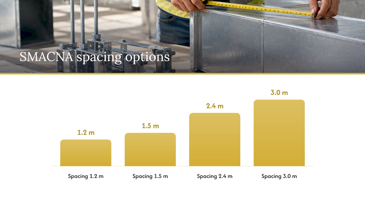
SMACNA publishes tables, not a single number, because duct construction varies by gauge, reinforcement, size, and pressure class. A schedule might offer a contractor the choice of 1.2 m, 1.5 m, 2.4 m, or 3.0 m intervals, and the correct choice depends on which combination of duct size and construction governs that run. Reading a SMACNA table means matching your actual duct dimension and gauge to the column that applies, not picking the widest spacing available because it reduces material and labour.
Project specifications often narrow that choice down for you. A public-sector mechanical specification out of Winnipeg sets hanger spacing at 3,000 mm for ducts up to 1,500 mm, while explicitly pointing installers back to SMACNA for the hanger configuration and spacing tables that apply to other sizes. That pattern, where the spec sets a baseline and defers to SMACNA for edge cases, is common across Canadian institutional and commercial jobs, and it means the spec document takes priority over any generic rule of thumb you might have memorized.
Manufacturer installation instructions add a third layer, and they can be the controlling document when the hardware itself limits your options. Cable-hung support systems, for instance, carry their own installation standards with practical cut-offs: spacing tighter than the manufacturer’s minimum can make the system difficult to install correctly, while spacing beyond the stated maximum risks deflection the hardware was never rated for.
When these three sources disagree, the hierarchy on most Canadian jobs runs:
- The project specification governs first, since it was written for that building and that engineer’s intent.
- SMACNA governs where the spec is silent or explicitly defers to it.
- Manufacturer instructions govern the specific hardware you are installing, especially where they are more restrictive than SMACNA.
That hierarchy matters because installers who default to “SMACNA allows 3.0 m” without checking the spec sheet are the ones who get flagged on inspection. The spec is a contract document. SMACNA is the reference it leans on. The manufacturer’s sheet is the hardware’s actual limit.
Quick reference table: common spacing values and their application
The numbers below cover the spacing ranges an installer will meet most often on a Canadian commercial or institutional job, with the source behind each figure.
| Duct type and size | Typical hanger spacing | Source |
|---|---|---|
| Small sheet-metal duct (light gauge, low pressure) | 1.2 to 1.5 m (4 to 5 ft) | SMACNA schedule, as referenced in NRC/CNB code crosswalks |
| Medium sheet-metal duct | 2.4 m | SMACNA schedule |
| Large sheet-metal duct | 3 000 mm | Winnipeg mechanical specification |
| Flexible duct | Per manufacturer installation instructions, often tighter than rigid duct | Manufacturer documentation |
The Winnipeg specification’s 3,000 mm figure applies specifically to ducts up to 1,500 mm and references SMACNA for configurations outside that range, which is why the table above splits small, medium, and large duct into separate rows rather than quoting one blanket number.
Flexible duct does not follow the same logic as rigid sheet metal. Its support intervals come from the manufacturer, not from a SMACNA rectangular-duct table, because flex duct sags and deforms differently under its own weight and has its own crush and kink tolerances.
A few conditions push spacing tighter than the table suggests, regardless of duct type:
- Higher internal pressure classes typically call for reduced intervals and added reinforcement.
- Any attachment point weaker than the duct material or hardware rating forces closer spacing to keep loads within the attachment’s capacity.
- Ducts near the upper end of a size bracket, close to the next size breakpoint, often warrant the tighter end of that bracket’s range rather than the wider one.
Treat the table as a starting point for layout, then confirm against the governing spec before cutting a single hanger strap.

Placement rules and layout: supports near elbows, branches and equipment
Spacing intervals tell you how far apart hangers go along a straight run. Placement rules tell you where a hanger has to go regardless of the interval, because loads concentrate at fittings and connections in ways a straight-run number does not capture.
- Place a support within about 0.6 m (2 ft) of every elbow. Elbows redirect airflow and weight at once, and an unsupported elbow is the most common point where ductwork sags or pulls at its seams.
- Place a support within about 1.2 m (4 ft) of every branch intersection. A branch takeoff adds a joint, a seam, and often a damper, all of which add weight and a point where the duct can twist if unsupported.
- Treat equipment connections as support points, not as the end of a run. A duct terminating at a fan, VAV box, or diffuser box still needs a hanger near that connection, since the equipment itself rarely carries the duct’s weight without added stress on the joint.
- Add a hanger at every offset or transition fitting, including reducers and transitions between round and rectangular duct, because the fitting changes the duct’s stiffness and shifts where it wants to flex.
- Shorten the interval on short runs rather than skip the hanger, since a 1.5 m stub between two fittings still needs at least one properly placed support, even if that falls short of the standard spacing distance for that duct size.
A short lateral takeoff off a main trunk is the case installers most often get wrong. The takeoff is short enough that it feels unnecessary to hang separately, but an unsupported branch puts a continuous bending load on the main trunk’s seam at the connection point. One hanger near the branch intersection, placed per the rule above, removes that load entirely.
A long straight run in an open ceiling plenum is the opposite problem: the spacing interval from the SMACNA or spec table applies cleanly, with no fittings to complicate placement, so the job is simply holding the interval consistent and verifying the upper attachment can carry the span.
Equipment connections deserve the most attention because they are where contractors cut corners under schedule pressure. A duct dropping into a rooftop unit or terminating at a fan inlet needs its own support independent of the equipment casing, since equipment vibration and thermal movement will work a joint loose over time if the duct’s full weight rests on that connection.
Attachment and hanger selection: strap, angle-and-rod and trapeze
Spacing on paper means nothing if the attachment underneath it cannot carry the load. Hanger hardware selection and upper-attachment capacity are what actually determine whether a given spacing interval holds up in service.
Strap hangers are the simplest and cheapest option, and they are also the most limited. Project specification patterns commonly cap strap hangers at around 500 mm of duct width, with anything larger required to move to trapeze or angle-and-rod assemblies instead, according to the Winnipeg specification excerpt. Beyond that size, a strap simply does not distribute the load across enough of the duct’s perimeter to stay effective at the specified interval.
Angle-and-rod and trapeze hangers take over where strap hangers stop being adequate:
- Angle-and-rod assemblies suit medium to large rectangular duct where a strap would concentrate too much stress on the duct’s bottom seam.
- Trapeze hangers suit the largest ducts and multi-duct runs, since a single trapeze can carry two or three parallel ducts on one set of rods.
- Rod and angle sizing should match the SMACNA or spec table for that duct size, not be sized by habit or whatever stock is on the truck.
The upper attachment, where the hanger meets the building structure, matters as much as the hanger type itself. Concrete inserts, joist clamps, and beam clamps each carry different load ratings, and a weak or improperly seated upper attachment can force a closer hanger interval even when the duct size and SMACNA table would otherwise allow a wider span. A beam clamp rated for the actual flange thickness it is gripping behaves very differently from one forced onto a flange it was not sized for.
Hardware practice rounds out the picture: locking nuts and washers at the rod connection stop vibration from backing a hanger out over time, and thread engagement on a rod coupling needs to be full, not just a turn or two, to hold the rated load. Whenever the attachment is weaker than the duct or the hardware, the spacing gets de-rated to whatever interval the attachment can actually support, regardless of what the duct-size table says.
For general horizontal support ergonomics outside the duct-specific standards, the installer checklist from Cables & Chips NYC on J-hook spacing covers similar attachment-capacity logic, even though it is written for low-voltage cabling rather than ductwork.
Pro Tip: Size the angle and rod to the duct-size column in the spec table during shop drawings, not on site; it avoids a mid-install substitution when the stocked hardware does not match what the inspector expects to see.
Installation details that affect stability: insulation, vapour barrier and deflection
A correctly spaced, correctly attached hanger can still cause a callback if the installation details around it are wrong. Three details cause most of the field problems: vapour barrier continuity, riser support, and deflection under load.
Vapour barrier continuity matters most on insulated supply and return runs, where a hanger strap that cuts straight through the insulation and vapour barrier creates a condensation point. Common Canadian specification practice calls for insulating the strap hanger itself and extending that insulation 100 mm beyond the insulated duct, per the Winnipeg specification, which keeps the vapour barrier sealed at the one point most likely to break it.
A short list of details worth checking before calling a run complete:
- Confirm the vapour barrier is taped or sealed around every hanger penetration, not just wrapped loosely over it.
- Support vertical risers independently from horizontal runs, since a riser’s own weight pulls straight down on the top connection rather than distributing along a span.
- Check for breakaway or fire-rated connections where a duct crosses a fire separation, since a rigid hanger through that assembly can defeat the separation’s intended performance.
- Watch for visible oil-canning or seam flexing on wider ducts, which signals the current spacing is too wide for that gauge even if it matches the table.
Risers deserve their own mention because installers sometimes treat a vertical run as just a horizontal run turned sideways. SMACNA guidance and most project specs call for supporting risers independently, anchoring the duct’s weight at a floor penetration or dedicated bracket rather than relying on the horizontal hangers above and below the turn to carry that load.
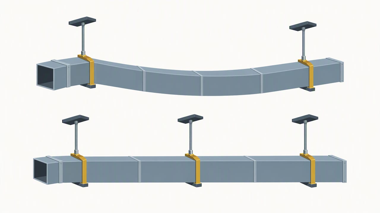
Deflection and buckling show up on longer spans carrying heavier gauge duct or higher internal pressure. A span that looks fine empty can sag visibly once the system is running at design pressure, particularly on reinforced duct where the reinforcement itself adds weight the original spacing calculation did not account for. When a run shows any visible sag between hangers, the fix is almost always to add an intermediate support rather than to re-tension the existing ones, since re-tensioning does nothing to address a span that was too wide from the start.
Common mistakes, inspection checklist and when to call an engineer
Most duct hanger problems on site trace back to a handful of repeated mistakes, not to unusual or complicated conditions.
The most frequent mistake is applying a pipe-hanger spacing table to ductwork. Pipe and duct have different support logic because pipe carries a concentrated line load along its length while duct is a thin-walled shell supported at discrete points, and the Winnipeg specification treats the two as separate hanger categories for exactly that reason. A spacing table built for 3/4 inch copper pipe has no bearing on a rectangular sheet-metal run, even though both get called “hanger spacing” in casual conversation.
Other recurring issues include undersized upper attachments that cannot carry the rated load, strap hangers used past the roughly 500 mm size cut-off instead of moving to trapeze, broken vapour barriers at hanger penetrations, and missing supports near elbows or branch takeoffs where installers assumed the straight-run interval alone was enough.
A short on-site checklist catches most of these before an inspector does:
- Confirm the governing spec and SMACNA table match the duct size and construction actually installed.
- Verify hangers exist within the standard distance of every elbow, branch, and equipment connection.
- Check that strap hangers are not carrying duct beyond their practical size limit.
- Inspect vapour barrier continuity at every hanger penetration on insulated runs.
- Confirm upper attachments are rated for the structure they are anchored to, not just seated and tightened.
Escalate to an engineer rather than guessing when a run falls outside normal conditions: unusually long clear spans with no intermediate structure, large-diameter high-pressure ductwork where deflection has real consequences, attachment types not covered by the standard hardware catalogue, or any project requiring seismic restraint design under Quebec’s CNESST workplace safety requirements. Those situations are where a spec table stops being enough and a stamped calculation becomes the only defensible answer.
Manara Corp.’s shop-to-field best practices for hanger-ready fabrication
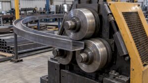
Sheet-metal duct sections and fittings are fabricated with CNC laser cutting, sheet bending and rolling, profile rolling, and welding, allowing hanger compatibility to be checked before a section reaches the site. A duct built to a dimension that does not match the spec table’s size column creates a hanger mismatch no installer can fix with field adjustments alone, so confirming duct width against the governing spacing table is a shop-floor step, not a site-floor one.
Matching angle and rod sizing to the spec table during fabrication, rather than after delivery, removes one of the more common causes of site delay. When a shop cuts and bends hanger plates and reinforcement angles to the exact dimension a SMACNA or project-spec table calls for, the installation crew hangs the section without needing to source a substitute bracket or re-cut a plate that does not fit. That coordination matters most on larger commercial runs, where dozens of identical sections all need the same hanger interface and a single dimensional error multiplies across the whole run.
Profile rolling and precision bending also apply directly to reinforcement details on larger ducts, since reinforced seams and stiffening angles need to land exactly where the spec table expects added support, not wherever is convenient to weld. Getting that placement right in the shop, where tolerances are controlled and every section can be checked against the same drawing, cuts down the kind of field rework that shows up when a reinforcement angle lands a few centimetres off from where a hanger needs to sit.
This work is fabricated and installed locally, which keeps fabrication drawings, shop checks, and the installation crew working from the same spec document throughout a project rather than handing off between a distant fabricator and a separate local install team.
Balancing code compliance, installation speed and cost
Tight schedules push installers toward the widest spacing a table allows, and most of the time that instinct is fine as long as the spec actually permits it for that duct size and construction. Where it stops being fine is on anything carrying higher pressure, anything with visible gauge flex between supports, or any run where the upper attachment is weaker than the hanger hardware itself. Those situations are not places to stretch the interval to save a few brackets.
The spec document and the manufacturer’s installation sheet are not suggestions open to field judgment. SMACNA gives a range because duct construction varies, but once a project spec picks a number from that range, that number is the contract requirement, and the manufacturer’s installation limits apply regardless of what the spec says if the manufacturer’s document is more restrictive.
On Greater Montreal jobs, the practical fix for most spacing disputes is reviewing the mechanical spec against the SMACNA reference during the shop-drawing phase, before fabrication starts, rather than debating interval choices on site once hangers are already cut.
— Ash
How Manara Corp. can reduce field labour with hanger-ready prefabrication
Ductwork that arrives from the shop already matched to the governing spec’s hanger dimensions saves a crew from the slowest part of any install: field fixes to parts that do not quite fit. Manara Corp. fabricates and welds custom air ducts in steel, stainless steel, and aluminum at its Lachine shop, using CNC laser cutting and sheet bending and rolling to hold duct dimensions and reinforcement placement to the sizes a SMACNA or project-spec table actually calls for.

That precision matters most where hanger spacing gets tight: large reinforced runs, transitions between round and rectangular duct, and any job where dozens of identical sections all need the same hanger interface. Fewer dimensional surprises on site means fewer substitute brackets, fewer re-cut reinforcement plates, and less time spent adjusting a section that should have fit the first time. The team fabricates in-shop and installs locally, keeping the shop drawing and the installation crew working from the same document throughout a project.
For a quote on custom fabricated ductwork or hanger-ready components for an upcoming job, reach out through Manara Corp.’s contact page or review the full range of fabrication services on the main site.
FAQ
What is the 2 foot rule for ductwork?
The 2 foot rule refers to placing a hanger within about 0.6 m of every elbow in a duct run, since elbows concentrate weight and stress at a fitting that a straight-run spacing interval alone does not adequately support. The same logic applies at branch intersections, typically within about 1.2 m, and at equipment connections.
What is the recommended spacing for pipe hangers?
Pipe hanger spacing follows its own tables based on pipe material, diameter, and fluid load, and those tables are not interchangeable with duct hanger spacing. The Winnipeg mechanical specification treats pipe and duct hangers as separate categories for exactly this reason.
How far should duct supports be placed?
Typical sheet-metal duct spacing runs 1.2 to 3.0 m depending on duct size and construction, with the Winnipeg specification setting 3,000 mm for ducts up to 1,500 mm and referencing SMACNA for other sizes. The governing project specification always takes priority over a general guideline.
What is the recommended hanger spacing for 3/4 inch copper pipe?
This figure comes from pipe-hanger tables, not duct-hanger tables, and applying it to ductwork is a common and incorrect substitution flagged in mechanical specifications. Installers should consult the pipe-specific hanger schedule in their governing project document rather than a duct spacing table for this value.
Can strap hangers be used on any duct size?
Strap hangers are generally limited to ducts up to around 500 mm, after which project specifications typically require trapeze or angle-and-rod assemblies instead. Beyond that size, a strap no longer distributes the load across enough of the duct’s perimeter to hold the specified interval reliably.