The K-factor in sheet metal is the ratio of the neutral axis distance from the inside face to the material thickness. It drives every flat pattern length you calculate. The core formula for extracting it from a test bend is K = ((BA / θ) − R) / t, where BA is the measured bend allowance, θ is the bend angle in radians, R is the inside radius, and t is the material thickness. The single most important practical rule: treat published K values as starting points and calibrate a shop-specific table from real test bends on your tooling.
The K-factor is not a material constant. It shifts with inside radius, material grade, bending method, and die geometry. A value that works perfectly on 3 mm mild steel with air bending will give you wrong flat lengths on 3 mm 6061-T6 aluminum.
Key takeaways
The K-factor defines where the neutral axis sits during bending, and getting it right from a shop-calibrated test bend is the only reliable path to accurate flat patterns.
| Point | Details |
|---|---|
| K-factor definition | K = neutral axis distance from inside face ÷ material thickness; ranges from 0.3 to 0.5 in practice. |
| Primary formula | BA = θ_rad × (R + K × t); extract K from test bends using K = ((BA / θ_rad) − R) / t. |
| R/T ratio drives K | Smaller inside radius relative to thickness pushes K lower; larger radii bring K toward 0.5. |
| CAD defaults are wrong | SolidWorks ships with K = 0.5; always replace with a shop-calibrated value before production. |
| Manaracorp can help | Manaracorp runs prototype test bends and production bending in Greater Montreal to validate your K table before full runs. |
Table of Contents
- What is the K-factor and how does the neutral axis behave?
- What actually shifts the K-factor?
- How to calculate the K-factor step by step
- How do K-factor, Y-factor, bend allowance, and bend deduction relate?
- Typical K-factor values by material and R/T ratio
- How to build a shop-specific K-factor table
- How CAD packages handle K-factor input
- Common flat-pattern errors and how to fix them
- Key formulas at a glance
- Why shop calibration is the only honest answer
- Precision bending in Greater Montreal with Manaracorp
- Sources
- FAQ
What is the K-factor and how does the neutral axis behave?
When sheet metal bends, the outer fibres stretch and the inner fibres compress. Somewhere between those two surfaces is a layer that neither stretches nor compresses: the neutral axis. The K-factor tells you exactly where that layer sits.
K = t_na / t
Where t_na is the distance from the inside face to the neutral axis, and t is the total material thickness. A K of 0.5 means the neutral axis sits exactly at mid-thickness. In practice it almost always migrates toward the inside surface during bending, so K typically falls below 0.5.
Key terms you need to keep straight:
- Inside radius ®: the radius at the inner surface of the bend, measured from the bend centre.
- Material thickness (t): the full sheet thickness before bending.
- Bend angle (θ): the included angle of the bend, in degrees or radians depending on the formula variant you use.
- Bend allowance (BA): the arc length along the neutral axis consumed by the bend.
- Bend deduction (BD): the total amount subtracted from the sum of the flat legs to get the overall flat blank length.
- Outside setback (OSSB): the distance from the bend tangent line to the apex of the bend.
The inside radius directly sets the K-factor, which in turn sets BA and BD. Change the radius on your drawing and you rewrite the flat pattern length. Always base flat development on the final specified radius, not an approximation.
What actually shifts the K-factor?
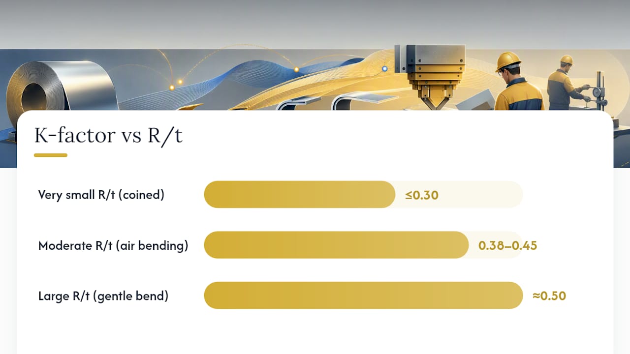
The R/T ratio is the dominant driver. As the inside radius shrinks relative to thickness, the neutral axis gets pushed harder toward the inside face and K drops. As R grows relative to t, the neutral axis approaches mid-thickness and K approaches 0.5. This is why a tight bend on thick plate gives a very different K than a gentle bend on thin sheet.
Material properties matter too. Higher-yield and work-hardening alloys resist deformation more uniformly across the cross-section, which tends to keep the neutral axis closer to mid-thickness and push K slightly higher. Softer, more ductile materials compress more readily on the inside, pulling K down. Harder alloys like 6061-T6 aluminium also carry a cracking risk at small radii, which is why some alloys require larger minimum bend radii to avoid fracture at the outer fibres.
Bending method has a real effect that many designers overlook:
- Air bending uses a punch and die with the sheet spanning the die opening. The punch does not bottom out, so the effective radius is controlled by the die opening and punch tip. K for air bending typically runs 0.38–0.45 for mild steel.
- Bottom bending (bottoming) drives the punch closer to the die, coining the material more aggressively. The neutral axis shifts further inward, lowering K.
- Coining applies enough tonnage to cold-work the material fully. K values for coined bends can drop to 0.3 or below.
Die opening width, punch tip radius, and friction between the sheet and die surfaces all contribute to the K you actually observe. Two shops using nominally identical tooling but different lubricants or die conditions can measure different K values for the same material.
Pro Tip: When you switch from air bending to bottoming on the same part, recalculate your flat patterns. The K shift is large enough to push a 90° bend out of tolerance on anything tighter than ±0.5 mm.
How to calculate the K-factor step by step
The two formulas you need
Extracting K from a measured test bend (radians):
K = ((BA / θ) − R) / t
Calculating bend allowance from a chosen K (radians):
BA = θ × (R + K × t)
For degree-based work, substitute θ_rad = (π / 180) × θ_deg.
Step-by-step procedure for measuring K from a test bend
- Cut a test blank of known total length (e.g., 200 mm) from the exact material and thickness you will use in production.
- Mark and bend it at 90° using your production tooling, die opening, and punch tip radius.
- Measure both flat legs (L1 and L2) with a digital calliper after bending.
- Calculate the actual flat blank consumed: BA = Total blank length − L1 − L2.
- Measure the actual inside radius R with a radius gauge.
- Confirm the actual bend angle θ with a protractor or angle gauge.
- Convert θ to radians: θ_rad = (π / 180) × θ_deg.
- Solve for K: K = ((BA / θ_rad) − R) / t.
- Repeat steps 1–8 at least three times and average the results.
- If K exceeds 0.5, clamp it to 0.5 — the neutral axis cannot lie outside mid-thickness.
Worked numeric example
Material: 3 mm mild steel, air bending, 90° bend, inside radius R = 3 mm.
- Total blank length: 200 mm
- Measured L1: 97.2 mm, L2: 97.2 mm
- BA = 200 − 97.2 − 97.2 = 5.6 mm
- θ_rad = (π / 180) × 90 = 1.5708 rad
- K = ((5.6 / 1.5708) − 3) / 3 = (3.565 − 3) / 3 = 0.565 / 3 = K ≈ 0.188
That result looks low, which would happen with a very tight R/T ratio (R/T = 1.0 here). Increase the inside radius to 4.5 mm and repeat: you will see K climb toward 0.33–0.38. This is exactly why the empirical test-bend method is more reliable than any published table for your specific setup.
Verify your K with at least three bends. A single measurement can carry gauge error. Average three results and check whether the spread is less than ±0.01 before committing the value to your CAD template.
How do K-factor, Y-factor, bend allowance, and bend deduction relate?
K vs Y-factor
The Y-factor is a stress-corrected version of K, defined as:
Y = (K × π) / 2
For K = 0.446, Y = 0.700. The Y-factor incorporates internal stress distribution across the bend cross-section, which makes it marginally more accurate in theory. In practice, the difference between K and Y predictions is small enough that most shops and CAD packages default to K. Y becomes worth the extra step when you are holding tolerances tighter than ±0.1 mm on a complex multi-bend part.
PTC Creo documents both factors in its sheet metal module and lets you choose which one drives the flat pattern. Most users stay on K unless a specific customer or process standard requires Y.
How BA and BD connect to K
Once you have K, bend allowance and bend deduction follow directly:
- BA = θ_rad × (R + K × t)
- BD = 2 × OSSB − BA
- OSSB = tan(θ/2) × (R + t)
The flat blank length for a simple two-leg part is: Flat length = L1 + L2 + BA (or equivalently, L1 + L2 − BD when using the deduction method).
When to use which:
- Use K when you need a single value that works across multiple bends in a CAD model.
- Use explicit BA when you have measured the actual arc length for a specific bend condition.
- Use BD when your press brake controller or CAD tool works natively in deduction mode.
| Method | Primary input | Best for | Shop practice |
|---|---|---|---|
| K-factor | K value (0.3–0.5) | General CAD design, multi-bend parts | Most common default |
| Y-factor | Y = (K × π)/2 | High-precision or stress-sensitive bends | Less common; Creo, some DIN workflows |
| Bend allowance | Measured BA | Known tooling, single-bend verification | Direct from test bend |
| Bend deduction | Measured BD | Press brake controller input | Common on the shop floor |
Typical K-factor values by material and R/T ratio
The commonly cited default K of 0.446 is a reasonable starting point for mild steel under air bending at moderate R/T ratios. It is not universal. Treat every value in the table below as a starting point that requires shop verification.
*6061-T6 requires larger minimum bend radii to avoid cracking; a tight R/T bend on this alloy risks fracture before K is even relevant.
Key points to keep in mind:
- K values above 0.5 are physically impossible — the neutral axis cannot migrate outside mid-thickness. If your calculation returns K > 0.5, recheck your measurements.
- Coining and bottoming shift K downward by 0.05–0.10 compared to air bending on the same material.
- Thicker material at the same R/T ratio tends to give slightly lower K than thinner sheet, because the through-thickness stress gradient is steeper.
How to build a shop-specific K-factor table
Reverse-engineering K from test bends is the most reliable method for a specific shop. Here is a repeatable procedure.
Test procedure
- Select three R/T ratios that cover your typical work: e.g., R/T = 1, R/T = 2, and R/T = 4.
- For each R/T, cut five identical blanks (e.g., 150 mm × 50 mm) from the same material lot and thickness.
- Bend each blank at 90° using your production punch, die, and settings. Record die opening, punch tip radius, and tonnage.
- Measure both flat legs with a digital calliper (resolution ≥ 0.01 mm). Measure the inside radius with a radius gauge. Confirm the angle with a digital protractor.
- Calculate BA for each sample: BA = blank length − L1 − L2.
- Solve for K using K = ((BA / θ_rad) − R) / t.
- Average the five K values for each R/T point. Discard any outlier more than ±0.02 from the group mean and note the cause.
Sample results log
Plot K against R/T. The curve is typically smooth and monotonically increasing, which means linear interpolation between tested points is reasonable. Where the curve bends sharply (usually at very low R/T), add an extra test point.
Pro Tip: Build a separate K table for each material-thickness-method combination you run regularly. A single shared table across all materials is the most common source of cumulative flat-pattern error in multi-bend assemblies.
When to update your table
Rebuild or revalidate your K table when:
- You receive a new material lot (yield strength can vary enough to shift K by 0.02–0.04).
- You change punch tip radius or die opening.
- You switch bending method (air to bottom, or vice versa).
- Parts start coming out of tolerance after a period of consistent production.
Store the validated K values in your CAD sheet metal templates, tagged by material, thickness, and tooling set. Experienced shops build interpolation tables across R/T points and update them whenever tooling or material batches change, which is the only reliable way to avoid cumulative dimensional error in complex parts.
How CAD packages handle K-factor input
Most professional CAD tools give you three choices for driving flat patterns: K-factor, bend allowance, or bend deduction. Onshape, for example, lets you select the method per bend, so you can use K for most bends and switch to explicit BA or BD for any bend where you have a precise measured value.
Key behaviours by platform:
- SolidWorks Sheet Metal: uses a global K-factor in the sheet metal feature, with the option to override per bend via a bend table. Default K is often 0.5 — check this before running any flat pattern export.
- Onshape: dropdown per bend lets you choose K, BA, or BD. K-factor is the recommended default for standard bends.
- PTC Creo: supports both K and Y-factor natively; the Creo documentation describes how each drives the flat pattern calculation.
- Autodesk Inventor: uses a bend table (.ipt format) where you can enter K values by material and radius. The default table ships with generic values that rarely match your shop tooling.
Practical verification steps:
- Export the flat pattern from CAD and measure the total developed length against your calculated BA.
- Bend a prototype and measure the actual leg lengths. If they differ from CAD by more than your tolerance, adjust K and re-export.
- For production runs, keep a signed-off prototype as the physical reference and compare the first article from each new material lot against it.
Pro Tip: Never trust a CAD default K without running at least one test bend. SolidWorks ships with K = 0.5, which is the theoretical maximum and almost always wrong for real bending conditions. A single unchecked default can throw every flat pattern in a complex assembly off by several millimetres.
Common flat-pattern errors and how to fix them
When bent parts consistently miss dimensions, the cause is almost always one of a short list of inputs being wrong.
Red flags to check first:
- Wrong inside radius in CAD: the radius on the drawing does not match the punch tip radius actually used. Even a 0.5 mm discrepancy changes BA meaningfully on thin sheet.
- CAD default K not updated: the software is using 0.5 or another generic value instead of your shop-calibrated number.
- Tooling mismatch: the die opening used in production differs from what was assumed during design. A wider die opening increases the effective bend radius and shifts K.
- Unaccounted springback: the part springs back after bending and the final angle is not 90°. This does not change K directly, but it changes the measured leg lengths and confuses the BA calculation if you measure before springback correction.
- Material lot variation: a new coil of nominally the same alloy has a different yield strength, shifting K by enough to matter on tight-tolerance parts.
Troubleshooting flow: confirm material thickness and grade, verify the die opening matches the drawing, run a test bend and measure K directly, update the CAD template, and re-export the flat. If parts are still off after correcting K, switch from K-factor mode to explicit bend allowance or bend deduction for that specific bend. Direct BA input removes one layer of abstraction and is the right call when you have a measured value you trust.
The Atlas Manufacturing guide makes a point worth repeating: always base flat development on the final specified inside radius. Changing the radius mid-project without recalculating K and BA is one of the most common sources of scrap in short-run fabrication.
Key formulas at a glance
The formulas below cover everything you need for daily flat-pattern work.
Bend allowance (radian form):
BA = θ_rad × (R + K × t)
Bend allowance (degree form):
BA = (π / 180) × θ_deg × (R + K × t)
Outside setback:
OSSB = tan(θ_deg / 2) × (R + t)
Bend deduction:
BD = 2 × OSSB − BA
K extraction from test bend:
K = ((BA / θ_rad) − R) / t
K to Y conversion:
Y = (K × π) / 2
For K = 0.446: Y = 0.446 × 3.1416 / 2 = 0.700. That 0.254 difference between K and Y is small but not zero — it matters when you are holding ±0.1 mm on a multi-bend part.
Units discipline matters. Mix degrees and radians in the same formula and every result is wrong. Pick one convention for a project and apply it consistently. Most shops work in degrees on the press brake controller and convert to radians only inside the BA formula.
Why shop calibration is the only honest answer
There is a temptation to treat the K-factor as a lookup problem: find the right table, pick the number for your material, and move on. That approach works well enough for prototypes where ±1 mm is acceptable. For production parts with real tolerances, it falls apart.
The reason is straightforward. The K-factor encodes the combined effect of material behaviour, tooling geometry, friction, and bending method into a single number. No published table can account for the specific combination of your punch tip radius, your die opening, your material supplier’s actual yield strength this month, and the lubrication your operator applies. A shop-calibrated table built from real test bends on your actual equipment does account for all of that.
The other thing practitioners underestimate is how quickly K drifts. A worn punch tip, a new material lot, or a switch from one die to another can shift K by 0.03–0.05. That sounds small. On a part with six bends, each contributing a few tenths of a millimetre of error, it adds up to a part that does not fit. The shops that avoid rework are the ones that treat K calibration as a maintenance task, not a one-time setup.
One more point worth making: the 0.446 default is not arbitrary. It is a reasonable approximation for mild steel at moderate R/T under air bending, derived from decades of press brake practice. It is a good starting point precisely because it is not far off for the most common case. The mistake is treating it as exact rather than as the beginning of a calibration process.
Precision bending in Greater Montreal with Manaracorp

Getting K-factor calibration right before production is the difference between parts that fit on the first bend and parts that go in the scrap bin. Manaracorp’s sheet metal shop in Lachine handles the full sequence: CNC laser cutting of flat blanks, precision sheet bending and rolling across steel, stainless steel, aluminium, and copper, and on-site installation throughout Greater Montreal — the island, Laval, the South Shore, and the West Island.
For designers and engineers who need prototype test bends to validate a K table before committing to a production run, Manaracorp can run calibration bends on your specified material and tooling setup and return measured results you can plug directly into your CAD templates. The same shop that runs your prototypes handles your production bending, so the K values stay consistent from first article to final delivery.
Request a quote or shop consultation to discuss your material, tolerances, and bend geometry. No job is too small or too large.
Sources
The following references were used to build this article and are worth bookmarking for deeper reading:
- Calculating k-factors for the press brake
- Mastering sheet metal bend calculations (Onshape tech tip)
- The basics of bend radii in sheet metal (Protolabs)
- About Y factor and K factor (PTC Creo support)
FAQ
What is the K-factor in sheet metal?
The K-factor is the ratio of the neutral axis distance from the inside face to the total material thickness (K = t_na / t). It determines how much material is consumed in a bend, which sets the flat pattern length.
What K-factor value should I use?
Start with 0.446 for mild steel under air bending at moderate R/T ratios, but derive your own value from test bends on your actual tooling. Published defaults are starting points, not shop-ready constants.
What does K-factor mean for steel specifically?
For steel, K reflects how the neutral axis shifts inward under bending load. Mild steel typically runs 0.38–0.44 at R/T ratios of 1–3 under air bending; harder or higher-yield steels tend toward the upper end of that range.
How is K-factor different from Y-factor?
Y-factor is a stress-corrected version of K, calculated as Y = (K × π) / 2. The two give very similar flat-pattern results for most shop work; Y adds a small accuracy improvement for tight-tolerance multi-bend parts but K remains the practical standard in most CAD tools and on the shop floor.