A complete fabrication drawing package must include a shop bill reconciled to the issued-for-construction documents, full fabrication geometry with datum references, weld symbols tied to an approved WPS, material traceability back to mill test reports, erection diagrams, and surface preparation notes. The fabricator checks the package for manufacturability and completeness, while the Engineer of Record reviews and seals it according to provincial practice guidance, measured against CSA S16, CSA W59, CSA W47.1, and the National Building Code.
TL;DR:
- Fabrication drawings must be based on current issued-for-construction documents, including full geometry, weld symbols referencing approved WPS, and material traceability reports to avoid rework.
- All referenced codes, material reports, welding procedures, and project specifications need to be current and complete before detailed fabrication work can begin.
- The verification checklist should include cross-checking shop bill reconciliation, geometry, material grades, weld accuracy, and erection details to prevent field issues.
- Different drawing types, such as assembly, detail, erection, and bills of material, serve distinct purposes and must be fully included to close the gap from design to installation.
- The responsible parties are the fabricator, who checks manufacturability, and the Engineer of Record, who reviews and seals the final package according to provincial standards.
Table of Contents
- What fabrication (shop) drawings are and when to prepare them
- Mandatory documents and contractual references to collect before issuing fabrication drawings
- Detailed checklist: 10+ technical items every fab package must verify
- Drawing types and deliverables: what each sheet must show
- Who reviews and seals the drawings: engineer of record, fabricator duties and PEO guidance
- Quality system expectations, inspection test plans and document control
- Common drawing errors, root causes and practical checks to avoid rework
- A shop-floor view on applying the checklist
- Fabrication-ready drawings and local installation from Manara Corp
- FAQ
- Sources
What fabrication (shop) drawings are and when to prepare them
Fabrication drawings, sometimes still called shop drawings, translate a structural engineer’s design intent into the exact geometry, connections, and material callouts a shop needs to cut, form, and weld a part. They differ from design or issued-for-construction (IFC) drawings in purpose: design drawings establish loads, member sizes, and governing forces, while fabrication drawings showpiece marks, bolt patterns, weld details, and dimensions ready for the shop floor. The CISC Code of Standard Practice now groups these under the broader term Fabrication and Erection Documents, and it states plainly that design documents must carry enough information to let a fabricator prepare them.
That dependency matters because fabrication drawings must be based on certified-for-construction documents, never on preliminary or for-information-only issues. Using preliminary data invites rework once dimensions, connection forces, or member sizes shift between issues, and a shop that cuts or welds against a superseded drawing set owns the resulting scrap and schedule slip.
Delivery formats vary by shop and contract, and most projects now combine several:
- Traditional 2D issued sheets, stamped and dated, for assembly, detail, and erection views.
- CNC or STEP files driving plasma, laser, or punch equipment directly from the detailing model.
- BIM exports, where the contract must state who owns the model, which level of development applies, and how changes propagate back to the issued sheets.
Mandatory documents and contractual references to collect before issuing fabrication drawings
Before a detailer opens a drawing file, a shop needs a defined document set on hand, not a partial folder assembled on the fly. Missing or outdated references are the single most common cause of fabrication errors that surface only after parts reach the field.
The minimum collection includes:
- Issued-for-construction drawings and the complete project specifications, confirmed as the current revision.
- Referenced codes and their standard editions, since a clause cited from an outdated edition can misstate a requirement.
- Material specifications and the mill test reports tied to the actual heat or lot being used.
- Approved welding procedure specifications (WPS) covering every joint type and position shown on the drawings.
- Approved shop notes or specification notes issued separately from the main drawing set.
- A List of Drawing Sheets, the project’s drawing index, confirming nothing has been dropped between issues.
Beyond the document list, a shop also needs to settle who owns the BIM model when one exists, because an unclear ownership chain leaves nobody accountable when a coordinate shifts between design and detailing. Request for information (RFI) records deserve the same treatment: every RFI answer that changes a dimension, connection, or material should be logged and cross-referenced against the drawing revision it affects, so a reviewer six months later can see why a detail reads the way it does. Contract-specified hold points, such as a required inspection before a coated assembly ships, need their own line in the document register rather than a note buried in a general specification. The TCP MTO fabrication document checking guidance frames this collection step as the foundation for everything that follows: a checker cannot verify completeness against a reference set that is itself incomplete or stale.
Detailed checklist: 10+ technical items every fab package must verify
Once the reference documents are confirmed, the verification pass itself follows a fairly consistent sequence across shops, whether the check is done by an in-house detailer, a third-party checker, or the Engineer of Record’s office. The TCP MTO checking guidance sets out at least ten technical elements a checker must confirm, and the list below expands on that core with the items shops report catching most often.
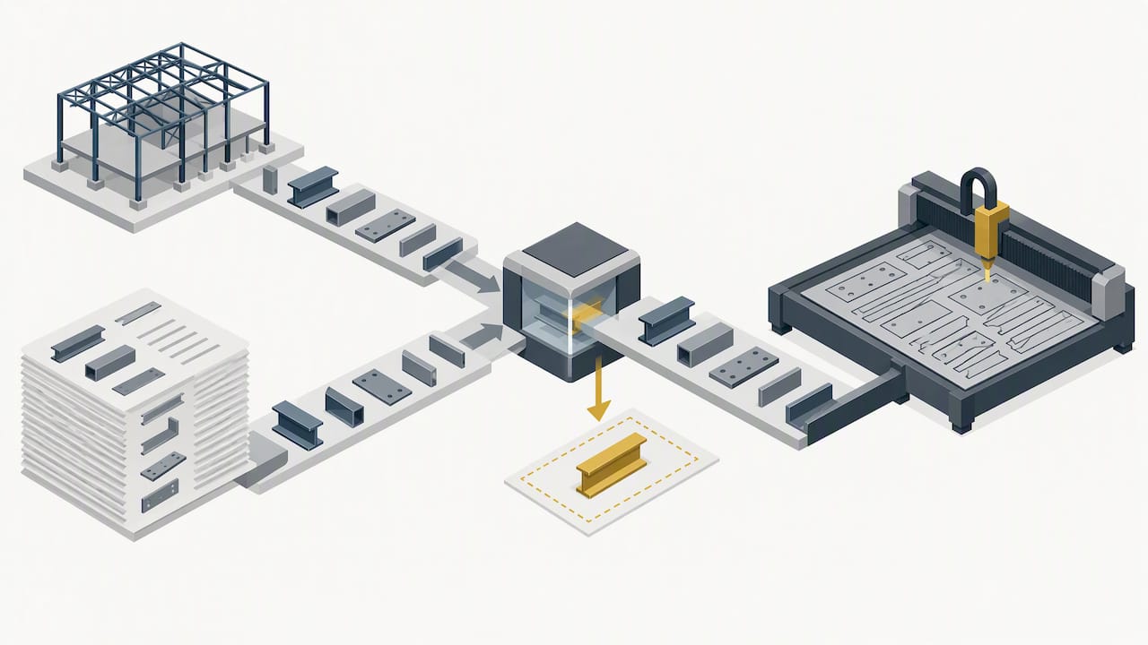
- Shop bill reconciliation: cross-check every piece mark on the shop bill against the issued-for-construction documents, confirming quantities, sizes, and grades match line for line.
- Geometry and dimensions: verify full fabrication geometry, including camber, matchlines, and datum references, so every member lands where the erection drawing expects it.
- Material grade and traceability: confirm the specified grade appears on the mill test report, and flag any substitution that needs engineering sign-off before cutting begins.
- Weld symbol accuracy: check that every weld symbol references an approved WPS and meets CSA W47.1 certification requirements, with NDT or inspection hold points called out where the contract requires them.
- Connection and bolt data: confirm connection forces, bolt types and grades, splice details, and anchor rod information needed for erection sequencing.
- Surface preparation and coatings: match coating specifications and surface preparation notes to the inspection acceptance criteria the contract defines.
- CNC file tolerances: verify file formats, nesting comments, and tolerance callouts for laser-cut or formed parts before the nest is released to the machine.
- Erection diagram completeness: check that setting elevations, splice installation sequence, and bolt torque or installation notes appear on the erection set, not just the shop details.
- Revision control: confirm the drawing carries the correct revision number, transmittal date, and the name of whoever approved or sealed it.
- Sign-off sequence: document which stage each check happened at, detailer self-check, independent checker, then Engineer of Record, so the approval trail is auditable later.
- Fit-up and tolerance stack: review tolerance stack-up across multi-piece assemblies, since individual parts within tolerance can still produce an assembly that will not fit.
Pro Tip: Run the shop bill reconciliation and a missing-member report before releasing CNC nests. Catching an omitted piece mark on screen costs minutes; catching it after cutting costs material, machine time, and schedule.
This sequence matters because each check depends on the one before it: there is little point verifying weld symbols on a geometry that has not been reconciled against the issued documents, and no point releasing CNC nests before tolerances are confirmed.

Drawing types and deliverables: what each sheet must show
Different sheets in the package carry different information, and a reviewer who knows what belongs where can spot a gap at a glance rather than hunting through an entire set.
- Assembly or general arrangement drawings show principal dimensions, piece marks, bolt and anchor data, camber, and cross-references to the erection drawings.
- Detail or shop detail drawings carry the full fabrication geometry: weld symbols, dimensional tolerances, fit-up notes, and explicit references back to the governing WPS and any required inspection.
- Erection diagrams give anchor rod locations and elevations, field splice details, and temporary bracing or erection sequence notes the site crew needs before steel goes up.
- Bills of material or shop bills itemize every piece with its material specification and a cross-reference to the mill test report backing that piece.
- Digital deliverables follow their own standards: CNC or STEP file naming and format conventions, nesting instructions, and, where a BIM model feeds the shop, a clear note on model ownership and level of development.
A package missing any one of these sheet types leaves a gap somewhere in the chain from design intent to installed steel, and that gap tends to surface at the worst possible moment: during erection.
Who reviews and seals the drawings: engineer of record, fabricator duties and PEO guidance
Responsibility for a fabrication drawing package splits between two roles, and blurring that split is where liability gaps open up. PEO’s practice guidelines define limits of responsibility for the primary structural engineer relative to other practitioners involved in review, and the guidance is explicit that a project should designate one clear Engineer of Record for design coordination and sealing.
- The Engineer of Record stays responsible for design intent throughout the project, including when a fabricator proposes a connection change for manufacturability.
- The fabricator checks drawings for manufacturability, flags interpretation issues, and routes genuine design questions back to the Engineer of Record rather than resolving them independently.
- A recommended workflow runs submit, then RFI or clarification questions, then revision, then final approval with the approving signature and date recorded.
- Record retention of the approval trail, who sealed what and when, protects both parties if a dispute surfaces well after the steel is installed.
PEO’s guidance treats this designation step as preventable risk management: ambiguity about who approves a connection detail is far easier to resolve before fabrication than after a disputed weld is already in place.
Quality system expectations, inspection test plans and document control
A fabrication drawing package does not stand alone. It sits inside a shop’s broader quality system, and the strength of that system is often what separates a package that sails through inspection from one that generates repeat RFIs.
The CISC Steel Fabrication Quality Guideline sets out the core components a shop’s quality system should carry:
- A Quality Manual describing how the shop controls its processes, from order intake through shipping.
- A Manual of Procedures detailing step-by-step practices for detailing, checking, and inspection.
- A controlled-document list identifying which revision of each drawing is currently valid for production.
- Document revision control and a defined retention policy for superseded drawings and transmittals.
These components map directly into an inspection and test plan (ITP): each verification step in the checklist earlier in this guide becomes a line item an inspector signs off against, with hold points matching the contract’s special inspection requirements. Mill test reports, inspection records, and approved shop drawings typically need multi-year retention to support later audits or liability reviews, and a shop that documents its own retention policy in its Quality Manual avoids scrambling to reconstruct records years after a project closes.
Common drawing errors, root causes and practical checks to avoid rework
Most fabrication drawing errors trace back to a handful of recurring causes, and knowing the pattern makes them faster to catch on review.
- Omitted items in the shop bill, usually from a late design revision that never propagated into the detailing model.
- Ambiguous weld symbols, where a symbol is technically present but does not clearly tie back to the correct WPS or joint position.
- Missing coating or workmanship notes, leaving the shop floor to guess at surface preparation grade or touch-up requirements.
- Mismatched datums or level callouts between the shop detail and the erection diagram, which only surfaces once steel is on site and refuses to line up.
A quick RFI template built around three questions, what changed, what document governs now, and what needs revision before cutting, resolves most ambiguity without waiting on a full formal response cycle. Reading weld symbols correctly is its own skill, and how to interpret weld symbol notation is worth a closer look for anyone checking a detail sheet for the first time.
Pro Tip: Reconcile the shop bill against the IFC model and generate a missing-member report before any CNC nest goes to the machine. That single step catches the omission category before it becomes a shop-floor problem.
A shop-floor view on applying the checklist
Checklists only earn their keep when a shop actually runs them before cutting, not after a part comes back wrong. We review every fabrication drawing against the issued-for-construction set before it reaches the shop floor, and we coordinate reviews in both English and French so nothing gets lost between a designer’s intent and a welder’s read of the sheet. That discipline, paired with local installation experience across Greater Montreal, is what keeps a package from turning into a field problem.
— Ash
Fabrication-ready drawings and local installation from Manara Corp
A checklist only prevents rework if the shop producing the parts can actually execute what the drawings call for. We handle laser cutting, sheet bending and rolling, profile rolling, and welding of steel, stainless steel, aluminum, and copper, all performed in-house and installed locally, which keeps quality control, code compliance, and timelines under one roof rather than split across subcontractors.

Whether the drawing calls for a laser-cut bracket, a formed and rolled profile, or a full custom staircase or railing run, we work from your issued-for-construction documents and produce fabrication-ready components without passing the file between separate shops. If you need a fabricator who can read a shop detail correctly, raise the right RFI, and still show up to install the finished piece, get in touch through our custom metal fabrication and welding services page to discuss your project.
FAQ
How many types of drawing are in fabrication?
A fabrication package generally includes four drawing types: assembly or general arrangement drawings, detail or shop drawings, erection diagrams, and bills of material. Some packages add digital deliverables such as CNC files or BIM exports as a fifth category alongside the traditional sheet set.
What are fabrication drawings?
Fabrication drawings translate structural design documents into the exact geometry, connections, and material information a shop needs to cut, form, and weld a part. They must be prepared from certified-for-construction documents, as the CISC Code of Standard Practice sets out, rather than from preliminary design issues.
How to read drawings for fabrication?
Start with the shop bill to confirm piece marks and quantities, then check the detail views for geometry, weld symbols, and tolerances, and finish with the erection diagram for setting elevations and splice sequencing. Weld symbols should always tie back to an approved welding procedure specification, and reading weld symbol notation correctly is worth learning before relying on a detail sheet.
What is the difference between an engineering drawing and a fabrication drawing?
An engineering or design drawing establishes member sizes, loads, and governing forces for a structure, while a fabrication drawing shows the shop-level detail, piece marks, weld symbols, and dimensions needed to actually build a part. PEO practice guidance treats the Engineer of Record as responsible for the former, while the fabricator checks the latter for manufacturability before production begins.
Who is responsible for approving fabrication drawings?
The fabricator checks the package for manufacturability and completeness, and the Engineer of Record reviews and seals the drawings for design intent, following provincial practice guidance on primary structural engineer responsibility. A clear submittal and RFI workflow keeps that approval trail documented for later reference.
Sources
Citing the right standards on the drawing itself, not just in a general specification binder, gives everyone downstream, from the welder to the inspector to a future auditor, a direct line back to the governing requirement.
The standards worth naming explicitly include:
- TCP MTO — fabrication document checking guidance
- Professional Engineers of Ontario — practice guidelines for structural engineering review
- CISC — Code of Standard Practice for Steel Construction
Citing the specific clause number and edition year, rather than just the standard’s name, matters more than it might seem. An edition change can shift a tolerance or a certification requirement, and a drawing that only says “per CSA W59” leaves a checker guessing which edition governed the design. Special cases deserve their own callout too: a bridge project pulls in CSA S6 alongside S16, and some provinces layer additional supplements on top of the national codes, so a drawing crossing into one of those categories should flag it plainly rather than leaving it implied.