A CNC press brake forms a bend by pressing a punch into a V-die while the controller manages ram depth and backgauge position, and the single most important control for repeatable work is matching the correct tooling to a programmed ram depth that accounts for springback. Everything else, from tonnage math to trial bends exists to protect that relationship. The three main methods, air bending, bottoming, and coining, trade force and precision differently, but they all live or die on that same pairing of tooling and depth control.
TL;DR:
- Matching tooling to the programmed ram depth is critical for repeatable bends, especially to account for springback and ensure angle accuracy.
- Using the correct V-die opening, roughly 6 to 8 times the material thickness, minimizes tonnage requirements and prevents cracking or excessive springback.
- Trial bending on scrap material and adjusting for actual springback is essential to avoid wasting good sheets and achieve precise angles in production.
- Widening the V-die, splitting long bends, or switching to higher-capacity machines prevents overloading when tonnage requirements are too high for the equipment.
- Regular calibration, tooling inspection, and verifying backgauge accuracy are vital to prevent common errors that cause inaccurate bends.
Table of Contents
- How a CNC press brake forms a bend
- Main bending methods: air bending, bottoming and coining
- Tooling selection and the V-die rule
- Programming, setup and trial bends: a step-by-step checklist
- Calculating tonnage and common pitfalls
- What causes inaccurate bends and how to troubleshoot them
- Safety and preflight checks for daily operation
- Shop practices in action: Manara Corp.’s approach to sheet bending and rolling
- Types and specifications of CNC press brakes
- Software tools and automation integration for CNC press brake programming
- Maintenance and calibration best practices for CNC press brakes
- Quality control and inspection methods post-bending
- Author perspective: shop habits that make bending repeatable
- How Manara Corp. handles sheet bending, rolling and installation
- Sources
- FAQ
How a CNC press brake forms a bend
Every bend comes down to five components working together: the punch (top tool), the die (bottom V-block), the ram that drives the punch downward, the backgauge that positions the sheet, and the control axes, X, Y, R, and Z, that coordinate them. The backgauge sets flange length by controlling how far the sheet sits from the bend line. Ram depth, the Y axis, determines bend angle. The R axis raises or lowers the gauge fingers to match material thickness, and Z shifts those fingers laterally for asymmetrical parts.
Three variables define the outcome of any bend: tonnage (the force applied), ram depth (how far the punch travels into the V), and tooling geometry (the punch angle and die opening). The CNC press brake controls ram depth and backgauge position together to produce consistent, repeatable results run after run.
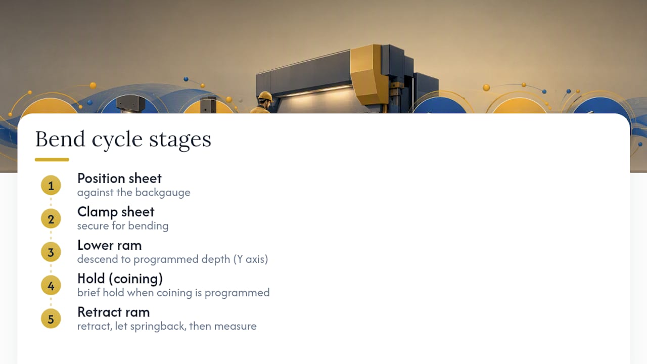
The bend cycle itself follows a fixed sequence: the sheet is positioned against the backgauge, clamped, the ram descends to programmed depth, holds briefly if coining, then retracts. Measure the angle and flange length only after the sheet has fully sprung back, never while it’s still under load.
Main bending methods: air bending, bottoming and coining
Air bending, bottom bending, and coining are the three primary methods used on any CNC press brake, and picking the wrong one for the job wastes tonnage capacity or accuracy you didn’t need to spend.
- Air bending presses the punch partway into the V-die without touching the die walls; it uses the least tonnage, adapts to any angle by changing ram depth, and is the most flexible and commonly used method for prototypes and mixed production runs.
- Bottoming drives the sheet fully against the die walls, requiring roughly three to five times the tonnage of air bending, and produces a tighter, more consistent angle with less springback variation.
- Coining forces the material into the die under much higher pressure, physically reshaping the grain structure at the bend, and delivers the highest achievable precision for parts with tight angular tolerances.
Use air bending for prototype and job-shop work where angles change often, bottoming for repeat production runs needing tighter control, and coining only when a part’s tolerance genuinely demands it, since the tonnage cost is steep.
Tooling selection and the V-die rule
Air bending depends on one rule above all others: the V-die opening should run roughly 6 to 8 times material thickness, with 8× being the common default for mild steel. Too narrow a V-opening spikes tonnage requirements and risks cracking the outer bend radius. Too wide a V-opening produces a sloppier, less controlled angle and increases springback variation.
Punch selection follows the part geometry:
- Straight punches handle standard open-angle bends on flat parts.
- Gooseneck punches clear tall flanges and box shapes where a straight punch would collide with the sidewall.
- Acute-angle punches pre-form angles tighter than 90 degrees before a final calibration hit.
- Radius punches protect thin or brittle material from cracking at the bend.
For mixed-length jobs, segmented tooling lets a shop cover multiple part widths without swapping full tool sets between runs, which cuts changeover time considerably. Full tooling details and options are covered in our guide to choosing press brake tooling.
Pro Tip: Check tooling alignment and clamping torque before the first production part, not after a bad batch. A punch sitting even slightly off-centre in the die throws angle accuracy across an entire run before anyone notices.
Programming, setup and trial bends: a step-by-step checklist
Getting from drawing to accepted first part is a sequence, not a guess. Skip a step and you’ll find out on the shop floor.
- Review the drawing and material. Confirm grade, thickness, and required tolerances before touching the controller.
- Select tooling. Match punch profile and V-die opening to the bend geometry and material thickness.
- Enter material and tooling data into the controller. Most modern controllers calculate suggested tonnage and ram depth once you input these values, and graphical programming interfaces can auto-sequence multi-bend parts and simulate collisions before the first hit.
- Program the axes and bend sequence. X sets flange length, Y sets depth and angle, R sets gauge height, Z shifts fingers laterally for offset bends.
- Run dry bends on scrap and measure. Adjust angle compensation based on actual results before committing good material.
Run five to ten trial bends on scrap from the actual batch, checking both angle and flange length each time, then dial in the controller’s angle compensation until two consecutive bends match. Skipping this step is how shops burn through good sheet on a bad first article.
Calculating tonnage and common pitfalls
A simplified air-bending tonnage formula looks like this: P = C × S² × L ÷ V, where P is tonnage required, C is a material constant, S is sheet thickness, L is bend length, and V is V-die opening width. The formula is a planning tool, not gospel. Actual tensile strength varies by alloy and heat treatment, so stainless steel demands noticeably more force than mild steel at the same thickness.
The thickness-squared term matters more than most operators expect. Double the sheet thickness and tonnage requirement doesn’t double, it roughly quadruples. A bend that needs 5 tons at 2 mm thick can jump toward 20 tons at 4 mm, all else equal.
When a part’s tonnage requirement outruns your machine, widen the V-die, switch to segmented tooling with lower per-station load, split a long bend into shorter passes, or move the job to a higher-capacity machine rather than forcing a marginal setup.
What causes inaccurate bends and how to troubleshoot them
Most bad bends trace back to one of four causes, and each has a direct fix.
- Wrong material data entered. Recheck the actual grade and thickness against the controller input, not the drawing assumption.
- Worn or mismatched tooling. Inspect punch tips and die edges for wear; swap tooling before it degrades angle consistency further.
- Inconsistent thickness or grain direction within the batch. Run dry test bends on scrap from every new coil or sheet lot before committing to production, and log the results against the previous batch.
- Backgauge miscalibration. Recalibrate against a known reference part if flange length drifts across a run.
If corrections don’t hold after retooling and recalibration, the part may need a different bending method entirely, moving from air bending to bottoming often stabilizes a stubborn angle.
Safety and preflight checks for daily operation
Before any production run, confirm tooling is clamped and properly aligned, verify the programmed tonnage sits within the machine’s rated capacity, and check that all guards are installed and functioning. Long or heavy sheets need proper support stands or a second operator, never a single person wrestling an unsupported panel through the bend cycle.
Quebec shops should keep CNESST machine-guarding and lockout requirements current, and structural or architectural work should follow applicable Canadian National Building Code provisions where the fabricated part becomes part of a building assembly.
Shop practices in action: Manara Corp.’s approach to sheet bending and rolling
A custom metal fabrication shop fabricates and installs metal work entirely in-shop, serving the Greater Montreal area with CNC laser cutting, sheet bending and rolling, profile rolling, and welding across steel, stainless steel, aluminum, and copper. Every job follows a consistent path: intake and drawing review, material verification against the order, program setup, trial bends on scrap, quality checks against the drawing, then local installation. That sequence mirrors the setup checklist above because it’s the same logic that prevents scrap on any properly run press brake.
Types and specifications of CNC press brakes
Hydraulic press brakes remain the shop standard, using oil-driven cylinders to move the ram and offering strong tonnage capacity across a wide range of machine sizes, from small 40-ton units up to several hundred tons for structural steel work. They’re forgiving of tooling variation and handle thick material well, but they run warmer and use more energy per cycle than newer alternatives.
Electric press brakes drive the ram with servo motors instead of hydraulics, which cuts energy use significantly and improves repeatability because there’s no oil temperature drift affecting ram position over a long shift. They tend to top out at lower tonnage ranges than large hydraulic machines, making them a better fit for lighter-gauge, high-precision work than for heavy structural bending.
Hybrid press brakes combine a hydraulic ram with servo-electric control over positioning, aiming to capture the tonnage capacity of hydraulics with the precision and energy efficiency of electric drive. They cost more upfront than a comparable hydraulic machine but reduce warm-up drift across long production runs.
Specification sheets worth comparing before buying or renting include tonnage rating, bed length, stroke length, open height, and the number of controlled axes. A machine with only backgauge (X, R) control handles simple parts fine; a machine with full X, Y, R, and Z axis control handles offset flanges and complex multi-bend parts without manual repositioning.
Software tools and automation integration for CNC press brake programming
Modern press brake controllers increasingly separate into two layers: the machine’s onboard controller for direct axis and tonnage control, and offline programming software that lets an operator build and simulate a full bend sequence before the sheet ever touches the machine.
Offline software typically imports a 3D model or flat-pattern drawing, calculates bend sequence order automatically, checks for tool and part collisions in simulation, and estimates tonnage per bend based on entered material properties. That collision check matters more than it sounds: catching a gooseneck punch that will hit a flange on bend four, before it happens on the shop floor, saves both tooling and scrap sheet.
Graphical programming interfaces also auto-sequence multi-bend parts, cutting setup time considerably compared to manually entering each bend step at the controller. That said, automation only reduces setup risk if the operator still verifies material inputs against the actual batch on hand and confirms the simulated sequence against the physical part orientation. Software can’t catch a mislabelled coil or an out-of-spec thickness; that verification stays a manual step regardless of how good the simulation is.
Integration with shop floor scheduling systems is growing too, letting a program built for one job get pulled up instantly when that part repeats weeks or months later, provided the shop has a habit of saving and naming proven programs consistently.
Maintenance and calibration best practices for CNC press brakes
A press brake that drifts out of calibration produces angle errors that look like operator mistakes but aren’t. Catching that drift early is a maintenance habit, not a troubleshooting exercise.
Daily checks should include a visual inspection of punch and die surfaces for nicks or wear, confirmation that clamping systems hold tooling without lateral play, and a check of hydraulic fluid level and temperature on hydraulic and hybrid machines. Weekly or monthly intervals, depending on run volume, should cover backgauge position accuracy against a known reference block and ram parallelism across the full bed length.
Ram parallelism matters more on longer beds. A ram that’s even slightly out of parallel produces a part with a consistent angle on one end and a slightly open angle on the other, a defect that’s easy to misdiagnose as a tooling problem when it’s actually a machine geometry issue.
Angle-measurement feedback systems, where fitted, should be recalibrated against a certified reference part on a set schedule rather than only when a problem shows up. CNC systems typically compensate for springback by over-bending and refine that compensation using angle feedback across a run, but that feedback loop is only as accurate as the sensor calibration behind it.
Tooling wear tracking deserves its own log. A punch tip that’s rounded from thousands of cycles changes the effective bend radius gradually, not suddenly, which makes it easy to miss until a part fails inspection.
Quality control and inspection methods post-bending
Every finished part should get checked against three things: bend angle, flange dimensions, and surface condition, in that order of priority for most structural and architectural work.
Angle verification typically uses a digital protractor or angle gauge against the programmed target, with tolerance bands set by the part’s application, structural railings tolerate more variance than precision enclosures. Flange length gets checked with calipers or a height gauge against the drawing dimension, accounting for the material’s actual measured thickness rather than the nominal spec sheet value.
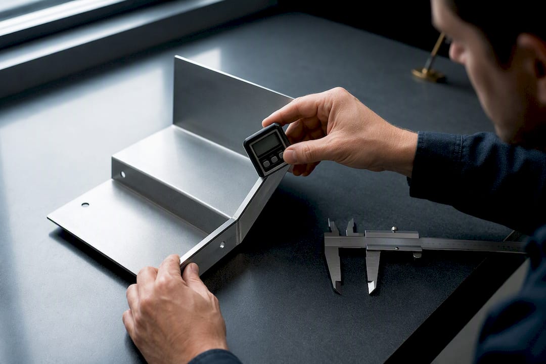
Surface inspection matters more than shops sometimes admit. Tool marks, scratches from misaligned dies, or cracking at the outer bend radius on thinner or more brittle material all show up here, and catching a cracked radius before a part ships prevents a much costlier field failure later.
For batch production, spot-checking the first, middle, and last part of a run catches drift that a single first-part inspection would miss entirely. If the middle part has drifted from the first, something changed mid-run, tooling heat, hydraulic temperature, or material batch variation, and it’s worth catching before the whole run ships.
Structural and architectural components, railings, stair stringers, and similar load-bearing work, should also get a fit check against connecting hardware or mounting points before leaving the shop, since a bend that’s technically within angular tolerance can still be functionally wrong if it doesn’t mate correctly with what it bolts to on site.
Author perspective: shop habits that make bending repeatable
The gap between a shop that fights scrap constantly and one that doesn’t usually comes down to habits, not equipment. Batch-test every new material lot before committing to production, save proven programs by part number so nobody re-programs a bend that’s already been solved, and log tooling life so a punch gets swapped on a schedule instead of after it’s already ruined three parts.
Pro Tip: Run a few warm-up bends on scrap before starting a precision job on a cold machine. Thermal expansion in the ram and tooling shifts dimensions slightly during the first several cycles, and skipping the warm-up is a quiet source of first-part rejects.
For parts with tight tolerances or unusual geometry, bringing in a local fabricator with the right tooling on hand often beats forcing a marginal setup through a machine that wasn’t built for the job.
— Ash
How Manara Corp. handles sheet bending, rolling and installation
Manara Corp. gives Greater Montreal fabricators, contractors, and homeowners a local alternative to sourcing bent sheet metal from out-of-area suppliers: everything is formed, checked, and installed by the same shop, on the same timeline, without shipping delays or a middleman between the bend and the install.

The shop offers CNC laser cutting, sheet bending and rolling, profile rolling, and welding across steel, stainless steel, aluminum, and copper, all fabricated in-shop and installed locally in the Greater Montreal area. Before reaching out, have your drawings ready, along with material grade and thickness, required tolerances, and target volumes, that information lets a shop quote accurately on the first pass instead of going back and forth. Whether the job is a single custom railing bracket or a full production run, get a quote through the sheet bending and rolling services page to start the conversation.
Sources
- CNC press brake bending: a fabricator’s fundamentals
- Press Brake Guide: Types, Working Principle, Tooling & Selection
- CNC press brake programming basics: step-by-step guide for beginners (2026)
- How to use a press brake machine: an operation guide – DUMACNC
FAQ
How do you bend sheet metal using a CNC press brake?
The sheet is positioned against the backgauge, clamped, and the punch presses it into a V-die to a programmed depth that sets the final angle, with air bending being the most common method for varied work.
What is the rule of 8 on a press brake?
It refers to sizing the V-die opening at roughly 8 times the material thickness for standard air bending, which balances tonnage requirements against bend quality on mild steel.
What are common mistakes on press brakes?
The most frequent errors are entering wrong material data into the controller, running worn or mismatched tooling, skipping trial bends on a new material batch, and letting the backgauge drift out of calibration.
What are the two main bending methods used on a press brake?
Air bending and bottoming are the two most widely used methods, with air bending pressing the punch only partway into the die and bottoming driving the sheet fully against the die walls for a tighter angle.
Who can help with custom sheet bending in Montreal?
A local fabricator provides custom bent and rolled sheet metal fabrication and installation services in Greater Montreal, from single brackets to full production runs.