Laser cutting thickness depends on one dominant factor: linear energy, the ratio of power to cutting speed, measured in joules per millimetre. As a rule of thumb, hobby and entry-level fibre lasers under 500 W handle up to roughly 6 mm of mild steel, production units in the 1 to 4 kW range reach 10 to 20 mm depending on material, and heavy 6 to 12 kW industrial systems push past 25 mm on steel. Assist gas and melt ejection decide whether that cut is clean or full of dross, so always confirm with a test cut before committing to a job.
TL;DR:
- Achieving maximum thickness with laser cutting relies on linear energy, which is the ratio of power to cutting speed, with different power ranges suited to specific materials and thicknesses.
- Reflective metals like aluminum and copper require higher power and slower speeds due to their reflectivity and thermal conductivity, unlike steel which cuts more easily.
- Adjustments such as focal spot position, assist gas type and pressure, and nozzle stand-off distance can significantly improve cut quality and penetration, especially on thicker materials.
- Test cuts with a detailed parameter log are essential to determine optimal settings for each material, thickness, and surface finish, ensuring repeatability and quality.
- Despite the advantages of fibre lasers in speed and precision, CO2 lasers can still perform better on some thicker sections depending on the specific material and cut geometry.
Table of Contents
- What thickness can each laser power band actually cut?
- How do power, focal spot and linear energy set the limit?
- Which power and gas settings work best for each material?
- Which process settings actually fix a bad cut?
- Does fibre or CO2 change how thick you can cut?
- How do you choose power and validate your settings?
- How do you measure and document cut quality?
- How does Manara Corp. apply this in the shop?
- When does a difficult thickness job need a professional shop?
- Get an accurate quote for your laser cutting project
- Sources
- FAQ
What thickness can each laser power band actually cut?
The table below reflects practical maxima drawn from fibre-laser cutting charts and cross-checked against experimental cutting research. Treat every number as a starting point, not a guarantee. Material grade, surface coating, and machine condition all shift the ceiling up or down.
A few things jump out once you sit with this chart. Reflective metals like aluminum and copper punch well below steel at every power band, because fibre-laser thickness charts consistently show suppliers recommending higher power and slower speed for these materials to compensate for reflectivity and thermal conductivity. Coated steel behaves closer to bare mild steel in raw thickness, but the coating changes fume handling and can leave a rougher edge if the assist gas pressure isn’t adjusted. Plastics cut differently altogether. Beyond a certain thickness, melting and re-solidification produce a worse edge than a thinner sheet cut at the right speed, so more power doesn’t always mean a better result on acrylic or HDPE.
How do power, focal spot and linear energy set the limit?
Linear energy, expressed as power divided by cutting speed, is the single number that tells you whether a laser will punch through a given thickness. A 3 kW laser running at 2,000 mm/min delivers roughly 90 J/mm. Double the speed and you halve the energy delivered per millimetre of travel, which is why slowing down is the first move when a cut fails to fully penetrate.
Focal spot size matters just as much, because it determines how concentrated that energy is at the workpiece. A tightly focused beam near its Rayleigh length puts more watts per square millimetre into the melt front, which drives faster, cleaner cutting on thin material. On thick plate, that same tight focus can actually work against you: the beam diverges before it reaches the bottom of the kerf, starving the lower section of energy and leaving dross behind. This is why many shops deliberately move the focal point lower into the material, sometimes several millimetres below the surface, when cutting anything past about 8 mm.
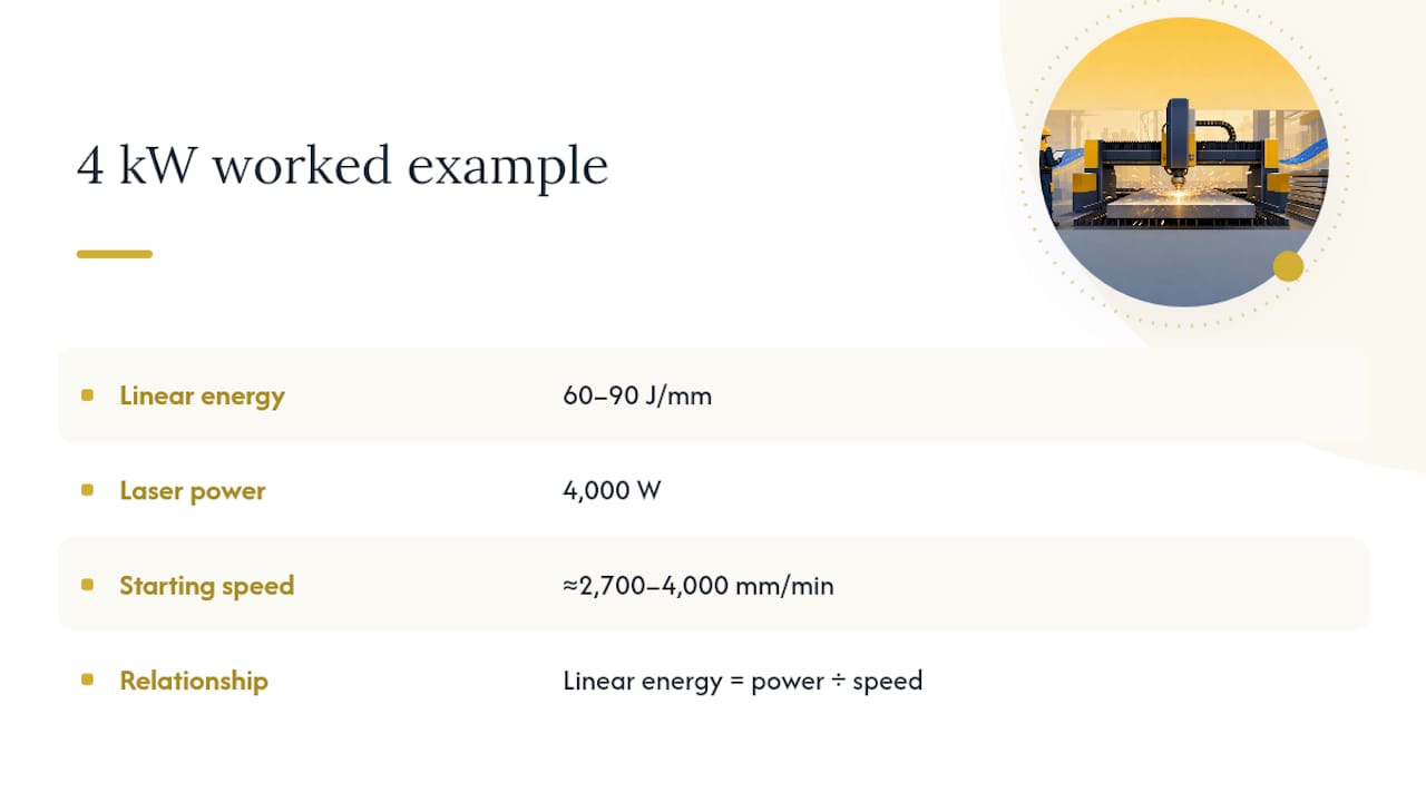
Here’s a worked example. Say you need to cut 10 mm mild steel and want a starting point for a 4 kW fibre laser. Industry cutting charts for this thickness band typically land in the 60 to 90 J/mm range with oxygen assist. At 4,000 W, that works out to a cutting speed between roughly 2,700 and 4,000 mm/min as your opening test setting. From there, you adjust in small increments, watching the kerf and bottom edge, rather than assuming the calculator number is production ready.
The factorial analysis of fibre laser cutting on AISI 304 stainless steel found that power, focal plane position, gas pressure, and nozzle diameter interact in ways that a single-variable calculation misses. Change one setting and the others often need re-tuning to hold the same edge quality.
Which power and gas settings work best for each material?
Every material has its own failure points, and most of them show up first at the thickness ceiling for that power band.
Mild steel responds well to oxygen assist, which adds an exothermic reaction to the cutting process and effectively increases both achievable thickness and speed compared to nitrogen. The trade-off is an oxide layer on the cut edge, which is fine for structural work but needs cleanup before painting or welding. Push past the practical maximum for your power band and you’ll see incomplete penetration at the bottom of the plate, often visible as a ragged, unmelted strip.
Stainless steel wants nitrogen, not oxygen, to avoid discolouration and preserve corrosion resistance at the cut edge. Fibre-laser tests on structural steel in the 4 to 6 mm range show quality declining noticeably beyond that band without deliberate parameter tuning, according to research on fibre-laser cutting accuracy in S355JR structural steel. Past 6 mm, expect to invest real time in a test matrix before you get a repeatable, dross-free edge.
Aluminum and copper are the two materials that punish underpowered setups the hardest. Both reflect a significant portion of the incoming laser energy and conduct heat away from the cut zone faster than steel, which means you need meaningfully more power per millimetre of thickness to achieve the same result. Expect slower cutting speeds even when the raw wattage looks generous on paper, and expect nitrogen at higher pressure than you’d use on stainless.
Coated metals and plastics carry their own hazards on top of the thickness question:
- Galvanized and zinc-coated steel release fumes that require proper extraction, and the coating can cause inconsistent striking at the start of a cut.
- Painted steel needs slightly reduced speed near the top surface to burn through the coating cleanly before the main cut begins.
- PVC and other chlorinated plastics should never be laser cut. They release corrosive and toxic gas that damages equipment and poses a real health hazard.
- Acrylic and HDPE cut cleanly at low to moderate power but tend to melt and re-fuse at the kerf edge past their practical thickness ceiling, producing a rounded rather than square edge.
If you’re unsure whether a coating or additive changes the picture, a shop that runs laser cutting daily can flag it before the job hits the table, which is one reason spec sheets and material certificates matter as much as the drawing itself.
Which process settings actually fix a bad cut?
Assist gas choice and pressure are the first levers to check when a cut isn’t performing. Oxygen increases cutting speed and thickness capability on carbon steel through its exothermic reaction, but too much pressure creates excess dross and a rougher edge. Nitrogen produces a cleaner, oxide-free finish on stainless and aluminum, though it demands higher pressure and a larger gas bill to get the same cutting speed as oxygen would deliver on steel.
Focal plane position is the second lever, and it’s the one most operators under-use. Defocusing the beam slightly below the top surface widens the effective spot size lower in the kerf, which helps push molten material out the bottom on thicker sections. This single adjustment often solves incomplete penetration faster than adding power.
Nozzle stand-off distance, nozzle diameter, and gas flow geometry round out the list. A nozzle sitting too far from the workpiece lets the gas jet disperse before it reaches the cut, weakening melt ejection exactly when you need it most on thick material.
When a cut fails, the fix usually follows a short diagnostic path:
- Incomplete cut at the bottom edge — slow the feed rate first, then check if the focal point needs to move deeper into the material.
- Heavy dross on the underside — increase assist gas pressure and confirm the nozzle stand-off hasn’t drifted.
- Excessive taper (narrower at the bottom than the top) — reduce speed slightly and verify the focal position is centred or slightly below the surface, not above it.
- Rough, striated edge — this often traces back to unstable gas pressure or a beam mode issue rather than raw power, according to the extensive review of laser cutting parameters and kerf quality, which found that low power with high speed, moderate gas pressure, and a small nozzle diameter consistently produced the lowest surface roughness on stainless and aluminum.
Pro Tip: Keep a running log of every parameter change and its result on a specific material and thickness. Six months in, that log becomes a faster reference than any generic settings chart, because it reflects your actual machine, not a lab bench.
Does fibre or CO2 change how thick you can cut?
Fibre and disk lasers operate at a shorter wavelength than CO2 systems, which means the beam absorbs more efficiently into metal and focuses to a smaller spot. That translates into faster cuts and lower roughness on thin-to-medium sheet, which is why most new shop installations in the last decade lean fibre.
CO2 hasn’t disappeared from the conversation, though. Research comparing industrial cutting outcomes across materials found that CO2 systems can retain an edge on some thicker-section cuts because of how the beam interacts with the cut-front geometry and melt ejection at greater depths. It’s not a universal advantage, but it’s a real one in specific material and thickness combinations.
Beam mode matters more than most buyers realize when they’re shopping on wattage alone:
- Gaussian beams concentrate energy at the centre and suit thin, precise work.
- Top-hat beams distribute energy more evenly across the spot, which can raise maximum cutting speed but risks burr formation at extreme speeds.
- Donut-shaped beams and beam oscillation are increasingly used to improve melt ejection on thicker stainless sections, and comparative testing across beam shapes confirmed that oscillation specifically improves cut quality where a standard beam struggles to clear molten material from a deep kerf.
Most of these beam-shaping options live behind the machine builder’s software, not the operator’s control panel, so ask directly what’s user-adjustable before assuming you can dial in oscillation on demand.
How do you choose power and validate your settings?
Start with the material and the finish requirement, not the machine you already own. A structural bracket tolerates more dross than a visible architectural panel, and that difference should drive your gas and speed choices before anything else.
The selection process breaks down into four steps:
- Specify the material, grade, and target thickness precisely, including any coating.
- Choose a conservative power band from the reference chart above, erring toward more power rather than less if the job sits near a threshold.
- Pick the assist gas based on material (oxygen for carbon steel, nitrogen for stainless, aluminum, and copper).
- Build a 3×3 test matrix: three cutting speeds against three gas pressures, holding power and focal position constant for the first pass.
On each test cut, measure the same things every time:
- Kerf width at the top and bottom of the cut.
- Dross adhesion on the underside, scored simply as none, light, or heavy.
- Surface roughness (Ra), by touch comparison or a profilometer if one’s available.
- Full penetration, confirmed visually or by light passing through the kerf.
Accept the setting once you hit full penetration with light or no dross and a kerf taper under roughly 1 to 2 degrees for the material class. Anything short of that calls for another matrix pass, adjusting one variable at a time rather than several at once, or accepting that manual deburring will be part of the post-processing plan for that job.
How do you measure and document cut quality?
Kerf width, taper angle, surface roughness, and dimensional deviation are the four measurements that separate a documented, repeatable process from guesswork. Kerf width is the gap the beam removes from the material, typically ranging from 0.1 to 0.5 mm depending on thickness and power, and it widens as plate gets thicker. Taper describes the angle between the top and bottom edges of the cut; a well-tuned setup keeps this close to vertical, while a poor one leaves a visibly wider top than bottom.
ISO 9013:2017 is the standard most fabrication shops reference for thermal cutting dimensional tolerances, and it’s worth having a copy on hand rather than relying on secondhand summaries when a client asks for a specific tolerance class.
Shop tolerance benchmark: Well-controlled laser cutting on flat stock routinely holds dimensional tolerances in the range of ±0.13 mm to ±0.05 mm, tighter than most mechanical cutting methods can achieve without secondary machining.
A simple documentation template covers material, thickness, power, speed, gas type and pressure, focal position, and the four measurements above for every accepted test cut. That record turns a one-off success into a repeatable process the next operator can follow without starting from zero. For a deeper look at how kerf geometry factors into part design, see this breakdown of kerf width and taper.
How does Manara Corp. apply this in the shop?
Manara Corp. runs CNC laser cutting in Lachine on steel, stainless steel, aluminum, and copper, and every job that comes through the shop gets a parameter check specific to that material, thickness, and finish requirement before full production starts. Tolerances on flat laser-cut parts commonly land between ±0.13 mm and ±0.05 mm, consistent with common shop-level benchmarks.
Test cuts can get documented as outlined earlier: material, gas, speed, and the resulting kerf and edge quality, helping maintain consistency for repeat orders. For jobs at the outer edge of practical thickness for a given material, shops may suggest outsourcing to a heavier-power provider rather than pushing an in-house machine past its comfortable range. When requesting a quote, include material grade, thickness, drawings with tolerance callouts, and any finish requirements up front.
When does a difficult thickness job need a professional shop?
Setup time is the first cost most people underestimate. Dialing in a reliable parameter set for an unfamiliar material or thickness through trial and error can eat a full day of machine time before a single production part gets cut. Equipment limits are the second factor: a machine rated for 4 kW simply won’t reach the linear energy needed for 20 mm steel, no matter how the settings get tuned.
Fume handling and safety around coated metals, reflective materials, and certain plastics push many jobs toward a shop with proper extraction and ventilation systems already in place. Before hiring, ask any fabricator directly about their maximum thickness by material, their assist gas capability, and whether they can share a documented test result for a comparable job.
— Ash
Get an accurate quote for your laser cutting project
Most online thickness charts give you a starting number, not a finished part. Manara Corp. is the alternative to guessing at settings on a rented machine or shipping a job to a shop outside the region: everything is cut, tuned, and inspected in-house in Lachine, with the same documented test-cut process described throughout this guide applied to every material, from mild steel railings to stainless and aluminum components.

Manara Corp. works in steel, stainless steel, aluminum, and copper, with laser-cut tolerances typically holding between ±0.13 mm and ±0.05 mm on flat stock. That range covers everything from structural brackets to architectural panels for custom railings and staircases across Greater Montreal, the West Island, Laval, and the South Shore.
When requesting a quote, provide material and grade, target thickness, drawings or sketches with any tolerance callouts, and finish requirements such as mill finish, paint-ready edge, or weld-prep bevel. Reach out through the laser cutting services page to start that conversation and get a realistic timeline for your project.
FAQ
How thick can laser cutting cut?
It depends entirely on laser power and material. Small-shop lasers under 500 W typically max out around a few millimetres on mild steel, while high-power industrial systems in the 6 to 12 kW range can cut significantly thicker materials, according to fibre-laser cutting thickness data.
How thick can a 100 W laser cut?
A 100 W laser sits at the low end of the small-shop power band and generally handles only a few millimetres of mild steel or common plastics at slow speeds. This wattage suits hobby and light craft work, not production-grade metal fabrication.
How thick can a 4,000 W laser cut?
A 4 kW fibre laser typically cuts mild steel up to medium thicknesses with oxygen assist, and stainless steel or aluminum somewhat less due to their different absorption and thermal properties. Actual results depend on gas pressure, focal position, and cutting speed, which is why a documented test cut matters more than the wattage figure alone.
How thick can a 20 W laser cut?
A 20 W laser is a hobbyist or engraving-class machine and generally cuts only thin materials like paper, thin wood, or light acrylic, rarely metal of any meaningful thickness. For actual metal fabrication work, you need machines in the hundreds of watts or higher, like the CNC systems Manara Corp. runs for custom metal fabrication projects.
What assist gas should I use for thicker cuts?
Oxygen suits mild and painted steel because it speeds the cut through an exothermic reaction, while nitrogen is the better choice for stainless steel, aluminum, and copper where a clean, oxide-free edge matters. Gas pressure needs to rise along with thickness to keep melt ejection effective at the bottom of the kerf.