Use ±0.005 in (±0.13 mm) as your baseline for standard laser-cut parts, and expect ±0.002 in (±0.05 mm) on precision fiber laser work when thickness and geometry cooperate. Ultra-tight tolerances below that are achievable on thin stock under controlled conditions, but they cost more and take longer. Specify tight tolerances only where a feature actually needs them, and always tell your supplier what kerf you assumed.
TL;DR:
- Standard laser cutting tolerances are around ±0.005 inches, with fiber laser precision reducing this to about ±0.002 inches under ideal conditions.
- Tighter tolerances are achievable only on thin materials (under 1.5 mm) with strict process control and come at higher costs and longer lead times.
- Material properties like reflectivity and thermal conductivity significantly influence the achievable precision, particularly on aluminum, stainless steel, and copper.
- Design considerations such as hole size, feature spacing, and part length impact tolerance success, making it essential to specify kerf compensation and critical features clearly.
- Proper file preparation, including explicit tolerance calls and material details, can prevent most tolerance disputes and improve production accuracy.
Table of Contents
- What tolerance levels can you actually expect from laser cutting?
- What factors change how tight your tolerance can be?
- How do you design parts that actually hit your tolerance target?
- How should you specify tolerances on a drawing?
- Why does tightening tolerance cost more, and when is it worth it?
- What should you check before sending files to a laser shop?
- Common tolerance mistakes and the one habit that fixes most of them
- Get a laser cutting quote from Manara Corp.
- Sources
- FAQ
What tolerance levels can you actually expect from laser cutting?
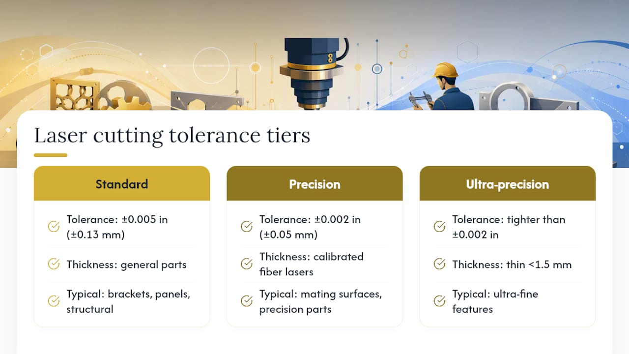
Most sheet metal shops quote laser cutting tolerances in three rough tiers, and knowing which one applies to your part saves a lot of back-and-forth on quotes. Standard shop tolerance sits around ±0.005 in (±0.13 mm), which covers the majority of brackets, panels, and structural components that don’t need mating surfaces. Precision work on a well-calibrated fiber laser tightens that to roughly ±0.002 in (±0.05 mm). Below that, you’re in ultra-precision territory, and it only holds reliably on thin materials under 1.5 mm with tight process control.
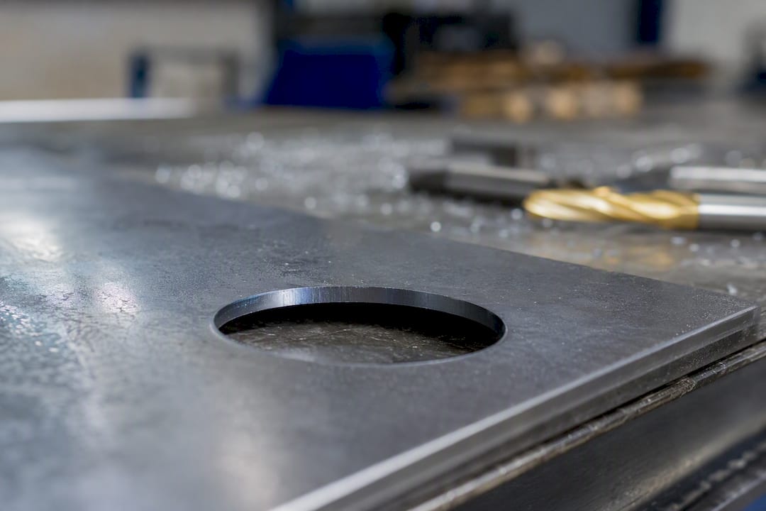
Kerf, the width of material the beam actually removes, typically runs 0.1 to 0.3 mm depending on thickness and gas type. That number matters more than most designers assume. A hole cut to nominal size comes out slightly undersized because the beam removes material from the inside of the path, while an outer profile comes out slightly oversized. If you don’t tell your CAM programmer which value to compensate for, you’re leaving that decision to guesswork.
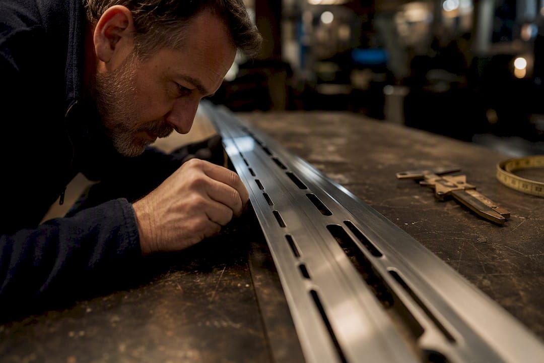
Repeatability drops as parts get longer. A 50 mm slot might sit comfortably inside precision tolerance, but a 2-metre contour accumulates thermal drift and machine backlash across its length, so the same nominal tolerance class doesn’t behave the same way on both. For longer runs or larger sheets, it’s worth budgeting a slightly looser tolerance on features far from the origin point, or breaking the part into smaller nested sections.
What factors change how tight your tolerance can be?
Material, thickness, and machine setup interact in ways that catch a lot of designers off guard, especially when a part that cut perfectly in mild steel comes back inconsistent in stainless or aluminum. Reflectivity and thermal conductivity are the two properties doing most of the damage.
- Stainless steel cuts cleanly with fiber lasers but its lower thermal conductivity concentrates heat at the kerf edge, which can widen tolerance slightly on thicker gauges.
- Aluminum reflects a meaningful portion of the beam, and its high thermal conductivity pulls heat away from the cut zone, both of which push toward looser achievable tolerance unless the machine is tuned for it.
- Copper is the hardest of the common shop metals to hold tight tolerance on, for the same reflectivity and conductivity reasons, and often needs specialized fiber settings.
- Thickness bands shift what’s realistic: under 1.5 mm you can chase precision or better; 1 to 6 mm is comfortable standard-to-precision territory; 6 to 12 mm loosens tolerance and softens edge squareness; above 12 mm, standard tolerance is usually the ceiling.
- Laser type matters more than most spec sheets admit. Comparative testing on 6 mm S235JR steel found fewer out-of-tolerance measurements on fiber-cut parts than CO2-cut parts, along with more repeatable surface roughness. Separate industry comparisons back the same conclusion for dimensional accuracy on steel.
- Geometry is its own variable: small holes near the minimum diameter, narrow bridges between features, and long unsupported contours are all more sensitive to heat buildup and vibration than a simple rectangular cutout.
- Machine condition rounds it out. Calibration drift, worn nozzles, loose fixturing, and poor part clamping will erode tolerance on a machine that’s mechanically capable of much tighter results.
Ambient conditions play a smaller but real role too. Temperature swings in a shop can expand sheet stock measurably over a large nest, and humidity affects assist-gas behaviour at the cut front. None of this shows up on a laser cut tolerance chart, but it’s part of why two shops running the same nominal machine specs can deliver different real-world results.
How do you design parts that actually hit your tolerance target?
Getting from a CAD file to an in-spec part comes down to a handful of habits that experienced designers apply almost automatically. Skip them and you’ll find out about the problem after the parts are already cut.
- Set minimum hole diameter to at least the material thickness, and ideally 1.5 times thickness for anything load-bearing. Smaller holes distort and lose roundness fast.
- Keep edge distance at a minimum of the material thickness from any hole or slot to the part’s outer edge, more on thicker stock, to avoid heat-affected bulging.
- Apply kerf compensation in your CAD model or CAM offsets, never both, and confirm which one your shop expects before the file goes out.
- Order a test cut on any first-run precision part before committing to a full production nest. It costs a little time and saves a lot of scrap.
- Use bridging tabs or micro-tabs on small or thin-walled features so they don’t warp or drop out of the sheet mid-cut.
- Nest parts with grain direction and thermal spacing in mind. Tight nesting concentrates heat and increases distortion across a run.
- Add a title block note covering material, thickness, tolerance class, assumed kerf value, and which features are functionally critical. This single habit prevents more disputes than any other item on this list.
Pro Tip: Mark critical features directly on the drawing with a tolerance callout, and leave everything else at the shop’s standard class. A drawing where every dimension looks equally important tells your supplier nothing about what actually matters.
Our own design rules guide walks through kerf compensation values in more detail, and the kerf-specific breakdown is worth bookmarking if you’re specifying a lot of hole patterns.
How should you specify tolerances on a drawing?
Two standards do almost all the work here, and knowing which one to reach for saves a round of clarifying emails with your fabricator. ISO 9013 classifies thermal cutting tolerances specifically, covering perpendicularity and dimensional deviation for laser, plasma, and flame-cut parts. ISO 2768 is the general tolerancing standard most designers default to on the title block, using classes f, m, g, and sg for progressively looser tolerance bands.
- Use ISO 2768 class f (fine) as your drawing default for parts with no unusual functional demands; it lines up closely with standard shop capability.
- Reserve ISO 2768 class m or coarser for non-critical structural or cosmetic parts where tighter tolerance would only add cost.
- Call out GD&T rather than a general tolerance class whenever you need positional control on a hole pattern, perpendicularity on a mating face, or true position on a bracket that has to line up with something else.
- Ask suppliers for a CMM report on features that carry GD&T callouts, and accept shop floor calliper or gauge checks for general dimensions.
- Request Cp/Cpk data on repeat production runs if the part feeds an automated assembly line; a one-off Cpk of 1.33 or better is a reasonable ask for a mature process.
- Confirm what surface metrics your supplier reports. Testing standards commonly reference Ra, Rz5, and perpendicularity deviation as the parameters that qualify cut edge quality.
Why does tightening tolerance cost more, and when is it worth it?
Tolerance and cost move together, but not in a straight line. Going from standard to precision tolerance adds a manageable premium. Chasing ultra-precision on a part that doesn’t need it can double or triple your per-part cost, and the reason is structural, not arbitrary.
- Inspection equipment scales up fast. Shop-floor gauges are enough for standard work, but precision claims usually require CMM verification, which adds time and labour to every part.
- Scrap risk climbs. Tighter tolerance means less margin for machine drift, so a higher percentage of parts fail inspection and get scrapped or reworked.
- Throughput drops. Precision cutting often runs at slower feed rates with more conservative gas and power settings, which reduces parts per hour on the same machine.
- The cost curve isn’t linear. Moving from ±0.13 mm to ±0.05 mm might add 10 to 20 percent to a part’s cost. Pushing further toward ±0.01 mm can multiply it, because you’re now fighting the physical limits of the process rather than just tightening a setting.
The practical fix is simple: tolerance your drawing feature by feature, not part by part. Apply tight tolerance only to the holes, edges, or mating surfaces that genuinely need it, and let everything else ride on the standard class.
What should you check before sending files to a laser shop?
A clean RFQ package prevents most of the tolerance disputes that happen after parts ship. Before you send a file anywhere, confirm you’ve included the following:
- Material spec and thickness, stated explicitly rather than implied by the CAD model.
- CAD files in a native or STEP format, not a flattened DXF that’s lost your fillets or hole callouts.
- Tolerance class or specific callouts on any feature that isn’t covered by your default drawing note.
- Your assumed kerf value, so the shop can confirm it matches their machine’s real-world cut width.
- Critical features flagged directly on the drawing, not buried in a separate spec document nobody reads until it’s too late.
- Inspection expectations, whether that’s a CMM report, a dimensional spot-check, or nothing beyond standard shop QC.
Manara Corp. runs both fiber laser cutting and in-house bending, rolling, and welding out of its Lachine shop, which means tolerance issues on a laser-cut part get caught before it moves to the next process step rather than after it’s already on a truck. That matters more than it sounds. A part that’s in spec off the laser but distorts during bending was never really in spec to begin with, and catching that requires the fabrication steps to talk to each other.
Pro Tip: Send your critical-feature list separately from the drawing PDF, even if it repeats information already on the title block. Shops that quote dozens of jobs a week appreciate not having to hunt for the one dimension that actually matters.
Common tolerance mistakes and the one habit that fixes most of them
The same three mistakes show up on drawings again and again: no stated tolerance class, no kerf assumption, and every dimension treated as equally critical. None of these are complicated to fix, which is what makes them frustrating. A designer who’s cutting corners on deadline defaults to “standard is fine” without checking whether a hole pattern actually needs positional control.
The single habit that prevents most of this: call out kerf explicitly and mark critical features on every drawing, every time, even when you’re confident the shop will “figure it out.” Confidence isn’t a tolerance spec. A five-second annotation saves a week of rework.
— Ash
Get a laser cutting quote from Manara Corp.
Manara Corp. cuts steel, stainless, aluminum, and copper on fiber laser equipment in its Lachine shop, then bends, rolls, and welds those same parts in-house, so tolerance decisions made at the laser stage carry through the rest of fabrication instead of getting lost between vendors. That’s the real advantage over sending a cut file to one shop and a bending job to another, with no tolerance stack-up between hand-offs and no guessing who’s responsible when a part comes back out of spec.

To get an accurate quote fast, send over your material spec and thickness, CAD or STEP files, any tolerance callouts on critical features, and your assumed kerf value. If you’re not sure which tolerance class fits your part, flag that too. The team can recommend a class based on the geometry and intended use. Start a quote through the laser cutting services page, or browse the precision and efficiency guide if you want a closer look at how Manara Corp. handles fitted assemblies before you send a file.
Sources
- Laser Cutting Tolerances: How Accurate Is Laser Cutting? (2026 Guide)
- The analysis of fiber and CO2 laser cutting accuracy (conference paper, DOI)
- Laser tolerances: engineers specify them and they are costing money
- Laser cutting tolerances — what to expect | LASERCUT
FAQ
Is 0.1 mm a tight tolerance for laser cutting?
Yes, ±0.1 mm sits between standard (±0.13 mm) and precision (±0.05 mm), so it’s achievable on most fiber laser setups but tighter than what many shops quote by default.
What is the accuracy of laser cutting?
Standard laser cutting accuracy runs around ±0.005 in (±0.13 mm), with precision fiber systems capable of roughly ±0.002 in (±0.05 mm) on suitable geometry and thickness.
What tolerance class does ISO 2768 use?
ISO 2768 defines four general tolerance classes, f (fine), m (medium), g (coarse), and sg (very coarse), with class f the common default for laser-cut sheet metal drawings.
What is the ISO standard for laser cutting tolerances specifically?
ISO 9013 governs thermal cutting tolerances directly, covering dimensional deviation and cut-edge perpendicularity, while ISO 2768 handles general part tolerancing.
Can Manara Corp. hold precision tolerances on stainless or aluminum?
Manara Corp. cuts stainless, aluminum, and copper on fiber laser equipment in its Lachine shop and can advise on realistic tolerance targets once material, thickness, and critical features are known.