Laser cutting kerf is the material removed by the laser beam as it cuts through a workpiece — the gap left behind between two cut edges. Industry guidance places typical kerf width between 0.08 mm and 1.0 mm, with fibre lasers on thin sheet often producing relatively narrow kerfs and high-power fibre lasers cutting thick plate producing wider kerfs. If you need a working number right now, cut a small test coupon in your target material. Measure the gap at the top and bottom of the cut with a digital calliper, and average the two readings. That single measurement is worth more than any table of nominal values.
Key takeaways
Laser cutting kerf is a fixed physical reality of the process — measure it in your target material, apply half-kerf offsets to mating features, and document the settings so every production run starts from a verified baseline.
| Point | Details |
|---|---|
| Measure before you design | Cut a test coupon in your target material and measure top and bottom kerf with callipers before finalising part dimensions. |
| Use the half-kerf rule | Offset outer profiles outward and inner holes inward by half the measured kerf per side to hold nominal dimensions. |
| Prototype mating parts | Cut one pair of mating parts and test the fit before releasing the full production run. |
| Document machine settings | Log nozzle type, gas type and pressure, focus position, and speed so results are reproducible across the job. |
| Manaracorp test cuts | Manaracorp offers in-shop calibration coupons and first-article verification for critical-tolerance laser cutting in Greater Montreal. |
Table of Contents
- What is laser cutting kerf and how does it form?
- What factors change kerf width and shape?
- What kerf widths should you expect by material?
- How do you measure kerf accurately?
- When and how should you compensate for kerf?
- Worked design examples using kerf compensation
- Common kerf problems and how to fix them
- Manaracorp’s shop calibration checklist
- What designers consistently get wrong about kerf
- Precision laser cutting and test cuts from Manaracorp
- Sources
- FAQ
What is laser cutting kerf and how does it form?
The laser beam focuses to a small spot on the material surface. At that point, energy density rises fast enough to melt or vaporise the metal. An assist gas — oxygen, nitrogen, or compressed air — blows through the nozzle and ejects the molten material downward, leaving a narrow channel: the kerf.
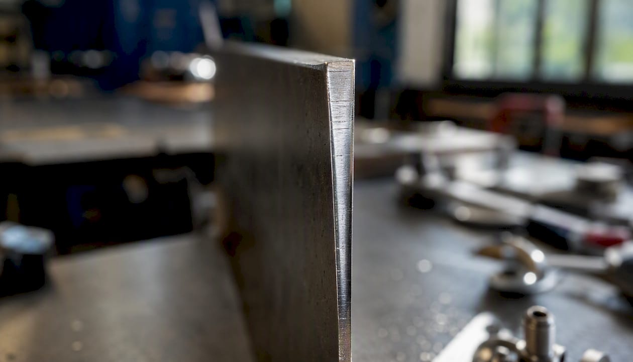
The channel is not perfectly rectangular. The top of the cut, where the beam enters, is typically wider than the bottom because the beam is most intense at the focal point and diverges slightly above and below it. On thicker plate, this taper becomes measurable. A rough rule of thumb is roughly 0.025 mm of taper per 2.54 mm of material thickness, though the actual figure shifts with machine setup and focus position.
CO₂ and fibre lasers behave differently here. CO₂ wavelengths (around 10.6 μm) produce a larger focused spot than the 1.06 μm wavelength of a fibre laser, so fibre systems tend to yield tighter kerfs on steel and aluminium at comparable power levels. That said, power class, optics quality, and focal length all interact — wavelength alone does not determine the outcome.
What factors change kerf width and shape?
Several variables move kerf, and understanding which ones matter most helps you control it or communicate clearly with a fabricator.
Machine and beam variables:
- Laser type and wavelength: fibre lasers generally produce narrower kerfs on metals than CO₂ at similar power.
- Beam profile: a 2026 study found that top-hat beam profiles produce surface roughness of Ra ≤ 2.6 μm at higher cutting speeds, while donut modes offer more stability on complex geometry at lower speeds — beam shape directly changes kerf geometry, not just edge finish.
- Power and cutting speed: higher power widens the kerf; faster speed narrows it. The balance between the two sets the heat input per unit length.
- Focal length and focal position: a longer focal length produces a shallower depth of focus and a slightly larger spot. Defocusing — intentionally or through drift — widens the kerf and degrades edge quality.
- Pulse frequency and duty cycle: relevant on pulsed systems; higher frequency tends to smooth the cut but can widen the heat-affected zone.
Assist gas variables:
Gas choice has a direct effect on laser cut edge quality. Oxygen promotes an exothermic reaction that adds energy to the cut, increasing speed but leaving an oxide layer on the edge. Nitrogen is inert, producing a clean, oxide-free edge — preferred for stainless steel and aluminium where weld-readiness or finish matters, despite the higher gas cost. Gas pressure, nozzle diameter, and standoff height all affect how efficiently melt is evacuated; poor evacuation leaves dross and can widen the effective kerf.
Material factors:
Thickness is the single biggest driver of kerf width. Beyond that, thermal conductivity, reflectivity, surface condition (mill scale, coatings, rust), and alloy composition all shift the result. Copper and brass are notoriously reflective and require specific process parameters; mild steel and stainless behave very differently even at the same thickness.
Pro Tip: Nozzle concentricity is easy to overlook. An off-centre nozzle skews the gas flow, producing asymmetric melt ejection and a kerf that is wider on one side. Check concentricity whenever you swap a nozzle.
What kerf widths should you expect by material?
The table below gives realistic starting ranges for common materials and thickness bands on a well-tuned machine. Treat these as planning values, not production tolerances — always verify with a test coupon before committing to a production run.
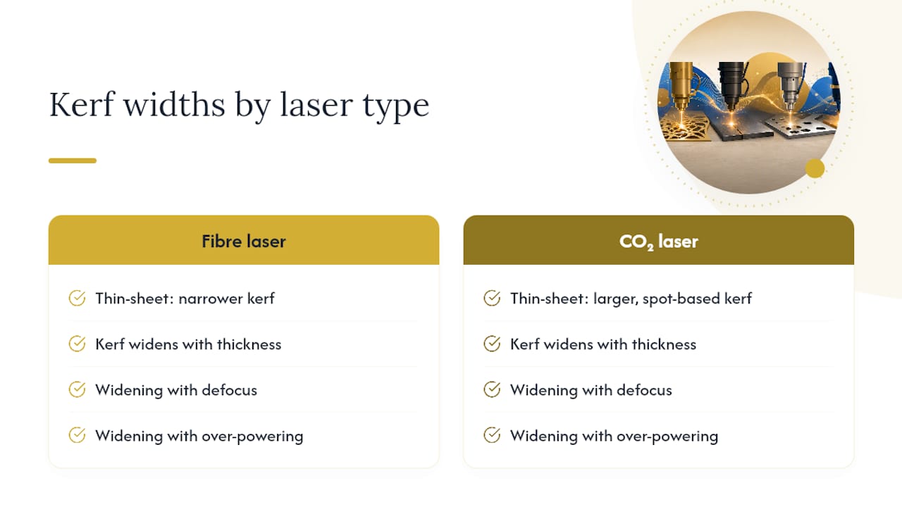
Kerf widens with thickness, with defocus, and with over-powering. Fibre lasers typically yield narrower kerfs on thin sheet while CO₂ processes show larger spot-based kerf bands. The numbers above assume clean optics, correct focus, and appropriate gas pressure — any deviation shifts them.
How do you measure kerf accurately?
A reliable kerf measurement follows a repeatable procedure. Guessing from a nominal table is how tolerance errors accumulate.
Test coupon design:
- A 100 mm × 100 mm square outline with two or three 10 mm circular holes and a 5 mm × 30 mm slot.
- Use the same material and thickness as the production job.
- Cut the coupon with the exact focus, nozzle, gas type, pressure, and speed settings intended for production.
Measurement steps:
- Let the coupon cool to room temperature before measuring.
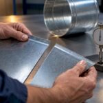
- Measure the width of a straight cut at the top surface and the bottom surface using a digital calliper or micrometer. Take three readings along the cut and average them.
- Measure the diameter of each circular hole at the top and bottom. Compare to the nominal CAD dimension.
- Apply the single-side gap formula: (nominal dimension − measured dimension) ÷ 2. For example, a 10 mm nominal hole measuring 9.70 mm gives (10 − 9.70) ÷ 2 = 0.15 mm per side.
- Record taper as the difference between top and bottom measurements.
Record the following for every test:
Save this log with the job file. When the same material and thickness comes back, you have a verified starting point rather than running a fresh test from scratch.
When and how should you compensate for kerf?
Compensate whenever parts must meet a dimensional tolerance or mate with another component. For rough prototypes where fit is not critical, skip it and save the setup time.
The half-kerf rule is the standard approach. The laser removes material symmetrically on both sides of the programmed cut path, so each side loses half the kerf width. To hold the correct finished dimension:
-
Outer profile (a tab or panel): offset the cut path outward by half the measured kerf.
part_offset = kerf ÷ 2
With a 0.15 mm kerf: offset = 0.075 mm outward. -
Inner feature (a hole or slot): offset the cut path inward by half the measured kerf.
hole_offset = kerf ÷ 2
With a 0.15 mm kerf: offset = 0.075 mm inward.
Where to apply the offset matters. Kerf compensation belongs in the CAM or machine controller, not as a blunt scale of the entire drawing. Scaling the whole design changes every dimension proportionally and breaks mating fits — it is not the same as a path offset. Confirm with your fabricator whether they apply offsets at the machine; if they do, do not also apply them in CAD or you will double-compensate.
For assemblies, decide on the fit type before setting offsets:
- Press fit: reduce the gap below zero (interference). Typical interference for a laser-cut tab-and-slot in 3 mm steel is 0.05–0.10 mm.
- Slip fit: allow a small positive clearance, usually 0.10–0.20 mm total gap for hand assembly.
- Structural weld fit: clearance of 0.20–0.50 mm is often acceptable since the weld fills the gap.
Pro Tip: Always cut a first-article test of mating parts before running the full job. A single pair of test pieces costs minutes; a full batch of mis-sized parts costs hours.
Worked design examples using kerf compensation
Tab-and-slot joint
Nominal tab width: 20.00 mm. Nominal slot width: 20.00 mm. Measured kerf: 0.15 mm.
- Tab offset: 20.00 + (0.15 ÷ 2) = 20.075 mm in CAD.
- Slot offset: 20.00 − (0.15 ÷ 2) = 19.925 mm in CAD.
- After cutting, the tab measures approximately 20.00 mm and the slot opens to approximately 20.00 mm — a slip fit with near-zero clearance.
- For a press fit, draw the tab at 20.10 mm and the slot at 19.925 mm, giving roughly 0.10 mm interference after kerf removal.
Press-fit peg in a hole
Nominal peg diameter: 8.00 mm. Nominal hole diameter: 8.00 mm. Measured kerf: 0.15 mm.
- Peg outer profile: offset outward by 0.075 mm → draw at 8.075 mm.
- Hole inner profile: offset inward by 0.075 mm → draw at 7.925 mm.
- Cut result: peg ≈ 8.00 mm, hole ≈ 8.00 mm. Add 0.05 mm interference to the peg for friction fit → draw peg at 8.125 mm.
Enclosure with interlocking tabs
An enclosure with six interlocking tabs per side accumulates kerf error at every joint. With a 0.15 mm kerf and no compensation, each tab-slot pair carries up to 0.15 mm of slop. Across six joints on one panel, the cumulative free play can reach 0.90 mm — enough to make the assembly feel loose and affect squareness. Apply the half-kerf offset to every tab and slot individually. Design-for-cutting guidance from Stanford’s making lab confirms that interlocking parts and enclosures require kerf offsets for fit; without them, the assembly tolerance budget is consumed before a single fastener is tightened.
Common kerf problems and how to fix them
Kerf too wide:
Check power against speed — the machine may be over-powered or running too slowly. Verify focus position; a defocused beam widens the spot immediately. Inspect the nozzle for damage or partial blockage.
Bottom dross (solidified melt on the underside):
Usually a gas pressure issue. Increase assist gas pressure incrementally. Also check cutting speed — too slow allows melt to re-solidify before ejection. On thick plate, a worn nozzle reduces gas velocity enough to cause persistent dross.
One-sided dross or asymmetric kerf:
Nozzle and gas problems often explain one-sided dross and kerf inconsistency. Check nozzle concentricity first. Optical contamination or a misaligned beam can also produce asymmetric energy distribution — this is a case where surface-level parameter changes will not fix the root cause.
Inconsistent kerf width along a cut:
Motion system issues (worn bearings, loose rack-and-pinion) cause speed variation that translates directly to kerf variation. Also check for thermal drift if the machine has been running for hours without a warm-up stabilisation period.
Burnt corners:
The machine is dwelling too long at direction changes. Reduce corner power or enable corner deceleration in the CAM software. Corners concentrate heat; a well-tuned machine reduces power automatically as it slows.
Maintenance quick-checks before escalating:
- Clean or replace the nozzle; inspect the orifice for ovality.
- Check lens and mirror cleanliness; a contaminated lens scatters the beam and widens the kerf unpredictably.
- Verify gas purity — moisture or oil contamination in the line degrades cut quality.
- Confirm standoff height with a feeler gauge or the machine’s auto-focus sensor.
Persistent taper that survives all of the above usually points to a beam-quality or optical alignment issue that requires a service technician.
Manaracorp’s shop calibration checklist
At Manaracorp, every production job that requires tight tolerances follows a structured calibration sequence before the first production sheet is loaded.
Calibration steps:
- Warm-up cut: run the machine for 10–15 minutes on scrap material to stabilise the laser source and motion system thermally.
- Standard coupon: cut the test coupon (square outline, holes, slot) in the production material and thickness.
- Measure and record: capture top and bottom kerf, hole diameters, and taper using digital callipers. Log all values with the nozzle type, standoff, gas type, and pressure.
- Verify nozzle concentricity: use the centering paper method or the machine’s built-in concentricity check.
- Sample assembly test: if the job includes mating parts, cut one pair and test the fit before releasing the full run.
- Freeze settings: once the coupon passes, lock the parameter file. No ad hoc adjustments during the run without re-running the coupon.
Regular maintenance and standardised test coupons are shop-level controls that stabilise kerf and edge quality. Assigning a single operator to a critical job and documenting first-article measurements reduces tolerance surprises across the run. For critical-tolerance work, a shop test cut before full production is the single most cost-effective step a designer can request.
What designers consistently get wrong about kerf
Most tolerance problems in laser-cut assemblies trace back to one assumption: that the machine will hold the nominal dimension without any input from the designer. It will not. Kerf is a physical consequence of the cutting process, and it shifts with every material change, thickness change, and machine state.
The most valuable habit is to test early. Cut a coupon on the first day of a new project, measure it, and build the offset into the CAD file before drawing the full part set. Designers who skip this step and rely on nominal kerf tables from the internet often find that their first prototype fits loosely or not at all — then spend time debugging a problem that a ten-minute test would have prevented.
Small kerf errors compound. A 0.10 mm error per joint across an eight-tab enclosure is 0.80 mm of cumulative slop. That is the difference between a tight, professional assembly and one that rattles. Iterate quickly on the coupon, not on the finished part.
Precision laser cutting and test cuts from Manaracorp
When tolerances are tight and the material is not forgiving, working with a shop that treats calibration as a standard step — not an extra — makes a measurable difference. Manaracorp’s CNC laser cutting services in Lachine cover steel, stainless steel, aluminium, and copper across a wide range of thicknesses, with in-shop test cuts available before any production run.

For critical-tolerance projects, Manaracorp can run a calibration coupon in your specified material, provide the measured kerf values, and confirm fit on mating parts before committing to the full job. That is the kind of first-article verification that saves rework. Manaracorp serves Greater Montreal — the island, Laval, the South Shore, and the West Island. To request a quote or book a test cut, visit the laser cutting service page or contact the shop directly.
Sources
- Laser cutting: a comparison of the performance of Gaussian, donut and top-hat beams, and an explanation of factors affecting cut quality and striation generation as a function of cutting speed | The International Journal of Advanced Manufacturing Technology
- Maximizing edge quality in laser cutting | The Fabricator
- What Is Laser Cutting Kerf? Width, Calculation & Compensation | DurmaPress
- Laser Cutting Edge Quality: What a Good Cut Looks Like | DraMetal
FAQ
What is laser kerf?
Laser kerf is the width of material removed by the laser beam during a cut — the gap between the two cut edges. It results from the beam melting or vaporising material, which is then ejected by the assist gas.
How much kerf should you expect in laser cutting?
Typical laser cutting kerf ranges from about 0.08 mm to 1.0 mm, depending on material, thickness, laser type, and machine settings. Fibre lasers on thin sheet commonly produce 0.10–0.25 mm; high-power fibre on thick plate can reach 0.60–1.00 mm.
Where should the kerf offset be applied when cutting?
Kerf offset should be applied in the CAM software or machine controller, not by scaling the entire drawing. Scaling changes all dimensions proportionally and breaks mating fits; a path offset adjusts only the cut line while preserving the intended geometry.
What causes inconsistent kerf width?
Inconsistent kerf width typically stems from motion system wear, focus drift, or optical contamination. Nozzle concentricity problems and inadequate gas pressure are also common causes, particularly when the inconsistency appears on one side of the cut only.