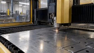
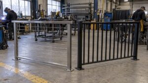
For most sheet metal work, expect cut-feature tolerances around ±0.13–±0.25 mm, formed and flange dimensions in the ±0.25–±0.76 mm range, and bend angles controlled to roughly ±1°. Dimension every critical hole or interface from a same-plane datum, or specify GD&T position, and reference ISO 2768 or ASME Y14.5 on the drawing rather than leaving defaults implied.
TL;DR:
- Tolerance stack-up is the main cause of fitting issues, so designing with worst-case or root sum square analysis is essential.
- Hole position errors increase after bending, so referencing flat, same-plane datums or adding secondary drilling can prevent misalignment.
- Tightening tolerances only makes sense for function-critical features or when a secondary operation can precisely control the dimension.
- Fabricators typically hold ±0.13 mm to ±0.25 mm for cut features, but form and bend tolerances are usually larger, around ±0.25 to ±0.76 mm.
- Explicitly specifying GD&T, referencing standards, and involving the fabricator early can significantly improve part accuracy and reduce rework.
Table of Contents
- What sheet metal tolerances should you expect on a drawing?
- Which tolerance type should you specify: linear, angular, or GD&T?
- How do laser cutting, bending, welding, and coating each add variation?
- How do you prevent tolerance stack-up from wrecking your assembly?
- How do you show tolerances clearly on a drawing?
- When is tightening a tolerance worth the extra cost?
- What does a real shop’s tolerance capability look like?
- What defects show up when tolerances go wrong, and how do you catch them?
- Does material thickness or alloy change what tolerances you can hold?
- Six quick rules of thumb for designers and engineers
- How Manara Corp. helps you get tolerance-critical parts right the first time
- Where to check the standards yourself
- Sources
- FAQ
What sheet metal tolerances should you expect on a drawing?
Cut features hold the tightest numbers because a laser or punch removes material in one pass with no compounding error. Typical laser-cut and punch tolerances run ±0.13 mm to ±0.25 mm, though nesting position, clamp shift, and heat buildup can widen that to ±0.10–±0.25 mm even on a well-maintained fiber laser.
Formed dimensions behave differently. Every bend adds its own error from springback and tooling wear, so flange and formed lengths typically land at ±0.25 mm to ±0.76 mm depending on thickness and how many bends stack up before that dimension closes out. Bend angle is often controlled within approximately one degree, and this angular variation can lead to measurable positional shifts on taller flanges.
Hole position tells a similar story. Holes punched or lasered on a flat blank, before any forming, sit near the tight end of the range. The same holes measured after bending, especially across a bend line, inherit the bend’s angular error on top of the original cut tolerance.
Keep these figures in mind when you set an RFQ baseline:
- Treat any tolerance tighter than ±0.13 mm as a special request, not a default.
- Ask your fabricator for their machine-specific numbers before finalizing a drawing.
- Never assume post-bend hole position equals the pre-bend cut tolerance.
Which tolerance type should you specify: linear, angular, or GD&T?
Linear (size) tolerances work fine for non-mating dimensions, like an overall bracket length that only needs to clear an opening. Angular tolerances cover bend angle and chamfer, usually expressed as ±1° unless the application calls for something tighter. GD&T position and profile controls earn their complexity when a hole pattern has to mate with another part, a fastener, or a moving assembly.
The rule of thumb: if a dimension only needs to fit inside a space, use a size tolerance. If it needs to align with something else, use position tolerance referenced to a datum. Datums should mirror how the part actually sits in the fixture or assembly, not an arbitrary corner of the drawing. Pick your primary datum from the largest, most stable surface, then build secondary and tertiary datums off features that control rotation and location.
- Use linear tolerances for clearance and cosmetic dimensions.
- Use angular tolerances for bend angle and any chamfer or notch angle.
- Use GD&T position/profile for hole patterns, weld-nut locations, and any interface with a second part.
Pro Tip: Before you tighten a ± dimension, ask whether the feature actually mates with something else. If it does, replace the linear callout with a GD&T position tolerance referenced to your fixturing datum, it almost always costs less to hold than an equivalent tight linear tolerance.
How do laser cutting, bending, welding, and coating each add variation?
Every process in the build order contributes its own share of error, and they don’t add up the same way twice.
Laser and punch operations set the baseline. A laser holds tight repeatability on a single part, but thermal distortion, sheet flatness, and nesting density all shift the practical window, which is why the same machine can post ±0.13 mm on one job and ±0.25 mm on the next.
Bending introduces the biggest variable: springback. Material grade, grain direction, and tooling wear all change how far the metal relaxes after the brake opens, and back-gauge repeatability adds its own scatter to flange length. On a part with three or more bends feeding into one critical dimension, that scatter compounds fast, which is exactly why treating every bend as an independent source of error rather than assuming it cancels out matters so much.
Welding adds heat-driven distortion, particularly on thin gauge stainless where warping shows up across long seams. Controlled weld sequencing and staged tack welds keep that in check, but they take planning, not correction after the fact.
- Confirm your fabricator’s kerf width and heat-affected zone before setting cut-feature tolerances below ±0.13 mm.
- Ask about back-gauge calibration frequency if flange length is a critical dimension.
- Specify weld sequence on drawings for parts prone to heat distortion.
- Add coating film thickness, typically 60 to 120 microns per side for powder coat, to any mating fit or slip joint dimension.
How do you prevent tolerance stack-up from wrecking your assembly?
Stack-up, not any single process error, is the most common cause of parts that don’t fit together on the shop floor. The fix starts with picking the right math and follows through with design choices that limit how many tolerances can compound in the first place.
- Choose worst-case analysis for safety-critical or low-volume stacks. It sums every tolerance at its extreme and guarantees the assembly fits, at the cost of tighter individual tolerances.
- Choose RSS (root sum square) for high-volume production. It treats tolerances statistically rather than assuming every part lands at its worst extreme simultaneously, which usually allows looser individual tolerances for the same assembly outcome.
- Design out the stack where you can. Same-plane datums, tab-and-slot features, and slotted rather than round holes absorb variation without needing tighter tolerances anywhere.
- Add a secondary operation for the one or two dimensions that truly need it, rather than tightening every dimension on the part.
Pro Tip: On any part with three or more critical interfaces, add a go/no-go gauge check right after the second bend. Catching a springback drift early costs you thirty seconds; catching it at final assembly costs you a scrapped part.
How do you show tolerances clearly on a drawing?
A drawing without an explicit tolerance block leaves the fabricator guessing, and guessing rarely lands in your favour. Set a default tolerance table in the title block, broken out by feature type: cut features, formed dimensions, and bend angles each get their own line rather than one blanket ± value for the whole part.
- State which standard governs unlabelled dimensions, for example “General tolerances per ISO 2768-m unless noted.”
- Call out GD&T datums explicitly on the feature, not just in a title-block note.
- Specify inspection conditions when they matter: room temperature, which face is “up,” and whether measurement happens before or after coating.
- Flag any secondary operation, like a post-bend drill or a tapped hole, directly on the affected feature so it isn’t buried in a general note.
When is tightening a tolerance worth the extra cost?
Tighter tolerances don’t scale linearly with price. They usually mean slower cycle times, added inspection, and sometimes dedicated tooling, and rationalizing tolerances on a tolerance-dense design can cut total cost by 15 to 30 percent without touching part function.
Before tightening anything, run through three questions: Is this dimension actually function-critical, or just a habit carried over from a machined-part drawing? Is there an assembly-level fix, like a slotted hole, that solves the fit problem without a tighter tolerance? Can a secondary operation handle just the one or two dimensions that need it, leaving the rest at shop-standard?
- Ask your fabricator for their standard tolerance table before writing custom numbers on the drawing.
- Flag only the dimensions that truly need tightening in your RFQ, not the whole part.
What does a real shop’s tolerance capability look like?
Manara Corp. reports laser-cut tolerances of ±0.13 mm to ±0.05 mm on its production equipment, numbers worth dimensioning against directly rather than guessing at a generic industry figure.
Take a bracket with a hole positioned 40 mm from a bend line. Dimensioning that hole from the bend edge inherits both the cut tolerance and the bend angle error. Moving the datum to the flat, same-plane edge before the bend, or planning a secondary drill after forming, removes that compounding entirely.
- Confirm capability numbers with your chosen fabricator before finalizing critical dimensions.
- Treat shop-published figures as a starting benchmark, not a guarantee for every material and thickness.
What defects show up when tolerances go wrong, and how do you catch them?
Hole misalignment is the most visible failure. A bracket that’s supposed to bolt flush instead sits proud on one side, usually traced back to a hole dimensioned across a bend rather than from a flat same-plane datum. A dial or pin gauge at final inspection catches it, but a go/no-go check right after bending catches it cheaper.
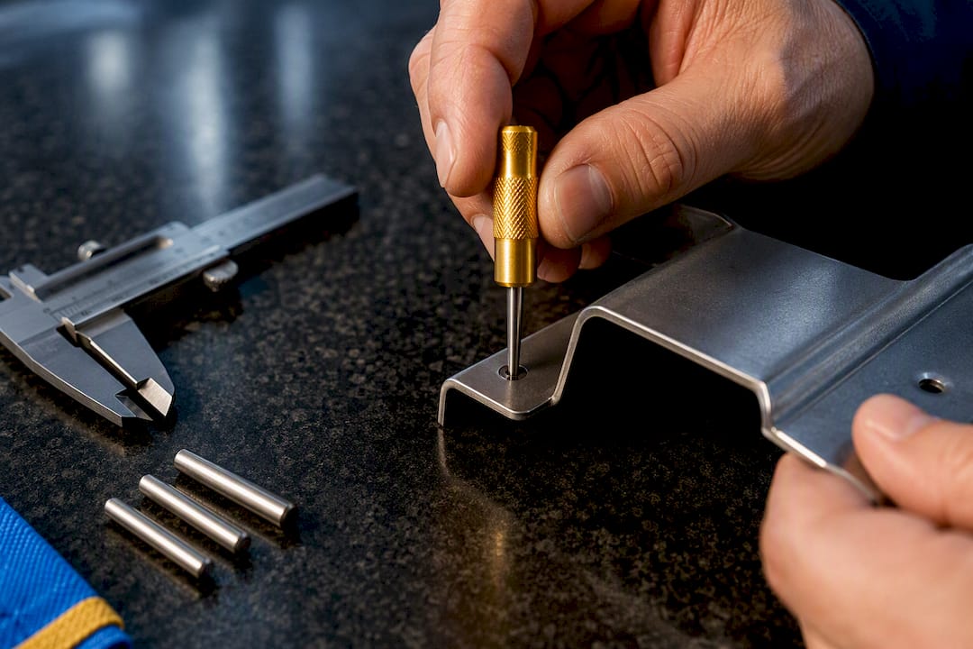
Gapping at welded or mechanical joints often comes from flange length drift. If springback wasn’t compensated consistently across a production run, one batch of parts closes tighter than the next, and assemblies that fit on Monday won’t fit on Thursday. Tracking flange length with a caliper on a sample from each run flags the drift before it reaches the customer.
Bow and twist show up on larger, thinner panels, usually from uneven cooling after welding or from residual stress released during cutting. A surface plate check or laser flatness scan on the first article of a run identifies this before it becomes a pattern.
Oversized or undersized holes, sometimes from worn punch tooling or incorrect kerf compensation in the CAM program, cause fasteners to bind or rattle. A pin gauge set is the fastest way to confirm hole size without a full CMM report.
The common thread across all four: catch them early in the process, not at final inspection. A process-capability map in CAM that sets default tolerances per material and thickness, paired with a quick gauge check after the second bend, stops most of these defects before they become scrap.
Does material thickness or alloy change what tolerances you can hold?
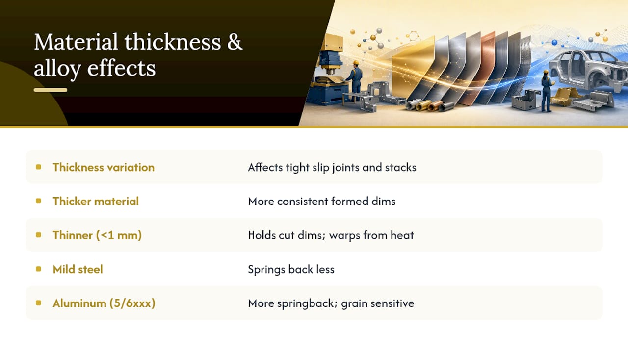
Thickness variation within a single sheet, typically a small percentage of nominal from the mill, shows up most on tight-fit slip joints and on parts where several sheets stack. A 3 mm plate that’s actually 3.1 mm across one corner of the sheet won’t cause problems on a bracket, but it will on a nested slip fit designed to ±0.1 mm clearance.
Alloy matters just as much as thickness. Mild steel springs back less than stainless steel of the same gauge, so a bend angle program calibrated for cold-rolled steel will under-bend a stainless part unless the brake operator compensates. Aluminum, particularly 5000- and 6000-series sheet, springs back more aggressively still and is more sensitive to grain direction, so a bend made across the grain and one made with the grain on the same part can land at slightly different angles.
Thicker material generally holds formed dimensions more consistently because it resists springback and handling deflection better, but it also needs more tonnage and a properly matched die, or the bend radius comes out inconsistent across a production run. Thin gauge, under about 1 mm, is the opposite problem: it holds tight cut tolerances easily but distorts more from welding heat and handling.
None of this means tolerances need to be looser by default. It means the fabricator needs to know the exact alloy, temper, and thickness before committing to a number on the drawing, not after the first batch comes back out of spec.
Six quick rules of thumb for designers and engineers
Dimension from same-plane datums, tighten only what’s function-critical, expect ±1° on bends, allow for coating thickness, involve your fabricator early, and use GD&T where fit actually matters. Build every RFQ around a solid model, a PDF drawing, and an explicit tolerance block.
— Ash
How Manara Corp. helps you get tolerance-critical parts right the first time
Manara Corp. is the local alternative to guessing at generic tolerance charts: you get a shop with published laser-cutting numbers, ±0.13 mm to ±0.05 mm, plus in-house sheet bending and rolling and welding of steel, stainless steel, aluminum, and copper, all fabricated and installed on-site across Greater Montreal.
Send Manara Corp. your solid model and PDF drawing, with your tolerance block spelled out, and the shop team reviews it for DFM issues before it ever hits the laser cutting floor, catching stack-up risks and unrealistic callouts before they turn into rework. Service covers the island of Montreal, Laval, the South Shore, and the West Island, with support in both French and English. Get a quote and DFM review started on your next drawing set.
Where to check the standards yourself
- ISO 2768: general tolerance classes for linear and angular dimensions.
- ASME Y14.5: GD&T datums, position, and profile controls.
- Machining tolerance specification guide for contrast against cut-feature sheet metal tolerances.
Sources
- ISO 2768 standard page
- ASME Y14.5 dimensioning and tolerancing
- Sheet Metal Fabrication Tolerances: Standards & Costs | EVS
- Sheet metal tolerance design guide | Aivon
- Sheet metal tolerances: Avoid fit issues & costly rework | Manufyn
FAQ
What are the tolerances for sheet metal?
Cut features typically run ±0.13 mm to ±0.25 mm, formed and flange dimensions ±0.25 mm to ±0.76 mm, and bend angles about ±1°, though exact figures depend on material, thickness, and machine capability.
What are the four types of tolerances?
ISO 2768 defines four general tolerance classes, fine, medium, coarse, and very coarse, applied to linear and angular dimensions that carry no individual tolerance on the drawing.
What is h6 and H7 tolerance?
H7 and h6 are ISO fit-system tolerance grades used mainly in machining and shaft/hole fits rather than sheet metal; a machining-focused tolerance specification guide covers these grades without specific tolerance numbers in this context.
What are the thickness tolerances for steel sheets?
Mill thickness tolerance varies by gauge and grade and is set by the steel supplier’s own specification sheet, not by a single universal figure, so confirm the exact allowance with your material supplier before dimensioning tight-fit features.
Can Manara Corp. hold tight tolerances on laser-cut parts?
Manara Corp. reports laser-cutting tolerances of ±0.13 mm to ±0.05 mm in-shop, and the team confirms exact achievable numbers for your specific material and thickness during a DFM review.